Welcome to the VHDL snippet library!
This page contains code examples that may be useful for the FPGA community.
When asked on the blog or in VHDLwhiz’s private Facebook group, I often write code to explain things. I will publish the examples on this page so that googlers and visitors to my blog can find and benefit from them.
Hit Ctrl+F (Windows/Linux) or Command+F (Mac) to search on this page.
2FF synchronizer
When introducing external signals into your design, you must not use them in any logic before synchronizing them to the local clock domain. That’s to avoid hazardous metastability problems that will cause your logic to behave unpredictably.
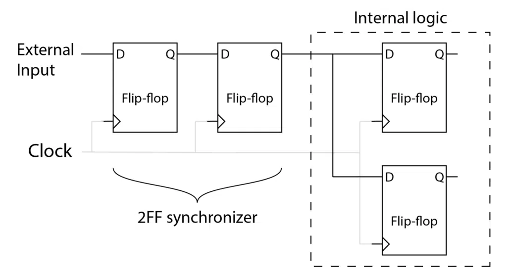
Fortunately, it’s easy to avoid metastability. All you have to do is send the external signal through two or more flip-flops (2FF) before using it. The code below shows one way to synchronize a signal in VHDL.
port (
  signal sig_async : in std_logic; -- Async input
  ... );
...

  signal sig_async_p1 : std_logic;
  signal sig_sync : std_logic; -- This one is safe to use

begin

  SYNC_PROC : process(clk)
  begin
    if rising_edge(clk) then
      sig_async_p1 <= sig_async;
      sig_sync <= sig_async_p1;
    end if;
  end process;
Fortunately, it’s easy to avoid metastability. All you have to do is send the external signal through two or more flip-flops before using it. The code below shows one way to synchronize a signal in VHDL.
The VHDL code will synthesize into this logic (the two flip-flops to the left):
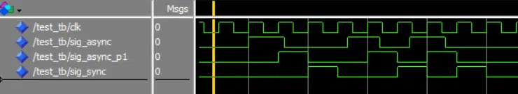
Here’s a waveform showing the synchronizer process in a simulation:
Do-while loop
The difference between a do-while loop and a regular while loop is that do-while tests the condition after each iteration. This means that the code block in the loop will run at least once.
Do-while loops don’t exist in VHDL, but they are easy to emulate. The example below shows a loop that waits at least until the next rising clock edge or until the next rising clock edge when tx_ready is asserted.
loop
  wait until rising_edge(clk);
  exit when tx_ready = '1';
end loop;
Place the condition at the end of the loop in an exit when statement, and you will get the same behavior as a C-style do-while loop.
Edge detector
There are many ways to design an edge detector in VHDL. Here’s an implementation that uses two helper signals, my_sig_is_rising and my_sig_is_falling, that are supposed to be read by other processes in the same module.
Make sure to synchronize my_sig before using it to avoid metastability if it’s an external signal coming into the FPGA.
port (
  signal my_sig : in std_logic;
  ... );
...

  signal my_sig_prev : std_logic;
  signal my_sig_is_rising : boolean;
  signal my_sig_is_falling : boolean;

begin

  EDGE_DETECTOR_PROC : process(clk)
  begin
    if rising_edge(clk) then

      my_sig_prev <= my_sig;

      my_sig_is_rising <= my_sig = '1'and my_sig_prev = '0';
      my_sig_is_falling <= my_sig = '0'and my_sig_prev = '1';

    end if;
  end process;
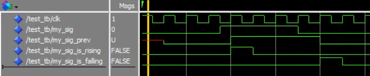
This waveform shows how the process reacts to a changing input signal:
Fork and join
VHDL doesn’t have fork and join constructs like SystemVerilog because it doesn’t need it. But you can easily implement execution branching in VHDL by using multiple processes and signals, as shown in this example testbench:
entity test_tb is
end test_tb;

architecture sim of test_tb is

    signal fork : boolean;
    signal join_1, join_2, join_3 : boolean;

begin

    CONTROLLER_PROC : process
    begin
        report "Forking";
        fork <= true;

        wait until join_1 and join_2 and join_3;
        report "Joined";
        fork <= false;

        wait;
    end process;

    PROC_1 : process
    begin
        wait until fork;
        report "PROC_1 started";

        wait for 10 ns;

        join_1 <= true;

        report "PROC_1 done";

        wait until fork = false;
        join_1 <= false;
    end process;

    PROC_2 : process
    begin
        wait until fork;
        report "PROC_2 started";

        wait for 5 ns;

        join_2 <= true;

        report "PROC_2 done";

        wait until fork = false;
        join_2 <= false;
    end process;

    PROC_3 : process
    begin
        wait until fork;
        report "PROC_3 started";

        wait for 15 ns;

        join_3 <= true;

        report "PROC_3 done";

        wait until fork = false;
        join_3 <= false;
    end process;


end architecture;
And the output to the simulator console will be:
# ** Note: Forking
#    Time: 0 ns  Iteration: 0  Instance: /test_tb
# ** Note: PROC_3 started
#    Time: 0 ns  Iteration: 1  Instance: /test_tb
# ** Note: PROC_2 started
#    Time: 0 ns  Iteration: 1  Instance: /test_tb
# ** Note: PROC_1 started
#    Time: 0 ns  Iteration: 1  Instance: /test_tb
# ** Note: PROC_2 done
#    Time: 5 ns  Iteration: 0  Instance: /test_tb
# ** Note: PROC_1 done
#    Time: 10 ns  Iteration: 0  Instance: /test_tb
# ** Note: PROC_3 done
#    Time: 15 ns  Iteration: 0  Instance: /test_tb
# ** Note: Joined
#    Time: 15 ns  Iteration: 1  Instance: /test_tb
Get even or odd bits from a std_logic_vector
This function will construct a new std_logic_vector of half length and return only the bits with even or odd indexes.
-- Return the even bits when even_not_odd = true
function even_or_odd(
  vec : std_logic_vector;
  even_not_odd : boolean) return std_logic_vector is
  variable ret : std_logic_vector(vec'length / 2  - 1 downto 0);
  variable mod_value : integer := 0;
begin

  mod_value := 1 when even_not_odd;

  for i in vec'range loop
    if i mod 2 = mod_value then
      ret(i / 2) := vec(i);
    end if;
  end loop;

  return ret;
end function;
For example, calling it with the vector "01010101010101010101010101010101" as shown below:
a <= "01010101010101010101010101010101";
wait for 10 ns;

b <= even_or_odd(a, true);
c <= even_or_odd(a, false);
Will return only the even bits and then only odd bits:
# a: 01010101010101010101010101010101
# b: 0000000000000000
# c: 1111111111111111
Click here to view the complete testbench.
Get the current date and time
You can easily get the current date and time during simulation and synthesis by using the TIME_RECORD that’s new in VHDL-2019. No such built-in feature exists if you are using a VHDL revision 2008 or lower, but you can use any of the following methods.
In Linux, it’s straightforward to extract the time using the /proc/driver/rtc file that provides information about the system’s real-time clock (RTC), including the current date and time. The code below shows how to do it in a testbench.
library ieee;
use ieee.std_logic_1164.all;
use ieee.numeric_std.all;

use std.env.finish;
use std.textio.all;

entity time_extract_tb is
end time_extract_tb;

architecture sim of time_extract_tb is

begin

  SEQ_PROC : process
    file rtp_file : text open read_mode is "/proc/driver/rtc";
    variable time_line : line;
    variable date_line : line;
  begin

    readline(rtp_file, time_line);
    readline(rtp_file, date_line);
    file_close(rtp_file);

    report date_line.all;
    report time_line.all;

    wait for 10 ns;

    finish;
  end process;

end architecture;
When run in the Questa simulator, the code prints out the following:
# ** Note: rtc date : 2020-07-21
#    Time: 0 ps Iteration: 0 Instance: /time extract_tb
# ** Note: rtc time : 10:21:18
#    Time: 0 ps Iteration: 0 Instance: /time extract_tb
# 1
# Break in Process SEQ_PROC at /home/jonas/time_extract/time_ extract.vhd line 31
If you are using Windows, you may have to use Tcl to make the timestamp available to the VHDL testbench. The code below shows an example of such a VHDL testbench.
library ieee;
use ieee.std_logic_1164.all;
use ieee.numeric_std.all;

use std.env.finish;

entity test_tb is
end test_tb;

architecture sim of test_tb is

  -- Stores a timestamp on the format: YYYY-MM-DD HH:mm:ss
  signal timestamp : string(1 to 19);

begin

  SEQ_PROC : process
  begin

    report "Hello from VHDL - timestamp: " & timestamp;

    wait for 10 ns;

    finish;
  end process;

end architecture;
You must also write Tcl code to force the timestamp string onto the VHDL signal from the simulator. The listing below shows how to do it in Questa. Paste the lines into the simulator console after compiling the VHDL testbench to run the demo.
vsim -onfinish stop work.test_tb
set timestamp [clock format [clock seconds] -format {%Y-%m-%d %T}]
force timestamp $timestamp
run -all
And the output to the transcript window will be:
# ** Note: Hello from VHDL - timestamp: 2023-08-21 10:58:48
#    Time: 0 ns  Iteration: 0  Instance: /test_tb
# Break in Process SEQ_PROC at C:/VHDLwhiz/test_tb.vhd line 24
Loop over string characters
This example shows how to loop over a string in VHDL and print the individual characters using a For loop. It works with constants, signals, and variables of type string.
  constant str : string := "Hello";

begin

  for i in str'range loop
    report character'image(str(i));
  end loop;
The output to the simulator console:
# ** Note: 'H'
#    Time: 0 ns  Iteration: 0  Instance: /test_tb
# ** Note: 'e'
#    Time: 0 ns  Iteration: 0  Instance: /test_tb
# ** Note: 'l'
#    Time: 0 ns  Iteration: 0  Instance: /test_tb
# ** Note: 'l'
#    Time: 0 ns  Iteration: 0  Instance: /test_tb
# ** Note: 'o'
#    Time: 0 ns  Iteration: 0  Instance: /test_tb
Required number of bits
You can use the following VHDL formulas to calculate the number of bits needed to represent a number. Both methods require that you import the math_real library, as shown below.
use ieee.math_real.all;
Use this code to calculate the number of bits it takes to store a given number:
-- Bits needed to represent the integer <max_val>
constant max_val : integer := 1024;
constant bits_needed : integer := integer(ceil(log2(real(max_val + 1))));

-- max_val: 1024, bits_needed: 11
Or if you need to find out how many bits you need to store N different values, you can use this calculation:
  -- Bits needed to represent the <values> number of combinations
  constant values : integer := 1024;
  constant bits_needed : integer := integer(ceil(log2(real(values))));

  -- values: 1024 (1-1023), bits_needed: 10
Typical use cases include calculating the width of a RAM address signal based on a generic constant. If max_val or values is the name of the generic, you could use the calculated constant to declare a signal of the correct size:
signal ram_addr : std_logic_vector(bits_needed - 1 downto 0);
Vivado: Export and import a project using Tcl
The Xilinx Vivado .xpr project files are binary and not suitable for version control or sharing with other people. Fortunately, Vivado has a write_project_tcl script that will let you export the entire project to a Tcl script suitable for checking into Git or packaging.
If you have any DCP (Design Checkpoint) files, you should delete them before exporting by going to Project Manager->Hierarchy->Utility Sources. Delete any .dcp files that are there because these binary files are not needed to recreate the project.
To produce the Tcl file, make sure you have the project open in the Vivado GUI. Then paste in the following two code lines in the Tcl Console:
cd [get_property DIRECTORY [current_project]]
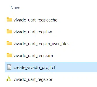
write_project_tcl -force -target_proj_dir . create_vivado_proj
That will produce a create_vivado_proj.tcl file in the Vivado project folder:
The script uses relative paths, so you must package it with the source files in the same relative paths as when you created the script.
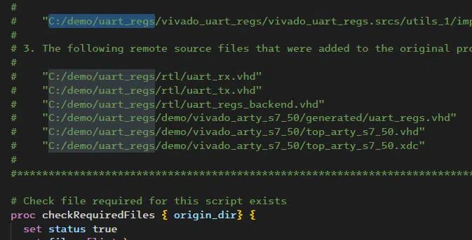
However, as shown below, the Tcl script will list the absolute path to the source files as comments in the header. Edit the header comment block if that bothers you.
Finally, you can delete the .xpr project files and folders and Zip the script with the source files in the same relative paths.
To recreate the Vivado GUI project, the user can navigate to the unzipped project directory in the Vivado Tcl Console and source the script to run it:
cd project_dir
source create_vivado_proj.tcl
Vivado: Set VHDL-2019 or VHDL-2008 for all .vhd files
To tell Xilinx Vivado to compile a VHDL file using the newer VHDL-2019 or VHDL-2008 revisions in the GUI, you can go to Project Manager->Sources->Compile Order, right-click the .vhd file, and select Source File Properties. Then, you can click the Type property and change the VHDL revision using the dialog box. You have to right-click every single file to make the change.
But you can easily change the VHDL revision of every single file in your project to 2019 by entering this command in the Vivado GUI’s Tcl Console:
set_property FILE_TYPE {VHDL 2019} [get_files *.vhd]
Or set all .vhd files to 2008 with this Tcl command:
set_property FILE_TYPE {VHDL 2008} [get_files *.vhd]
Thanks to David Lutz from the VHDLwhiz Membership comment section for this snippet!
Write to a file from multiple VHDL processes
This demo testbench shows how to write to an output file during simulation from several different processes, three in this example.
library ieee;
use ieee.std_logic_1164.all;
use ieee.numeric_std.all;
use std.env.all;

use std.textio.all;

entity test_tb is
end test_tb;

architecture rtl of test_tb is
  constant filename : string := "out_file.txt";

  signal msg1, msg2, msg3 : string(1 to 7);

begin

FILE_WRITER_PROC : process
  variable out_line : line;
  file out_file : text;
  variable status : file_open_status;
begin

  file_open(status, out_file, filename, write_mode);

  loop
    wait on msg1, msg2, msg3;

    if msg1'event then
      write(out_line, msg1);
      writeline(out_file, out_line);
    end if;

    if msg2'event then
      write(out_line, msg2);
      writeline(out_file, out_line);
    end if;

    if msg3'event then
      write(out_line, msg3);
      writeline(out_file, out_line);
    end if;

  end loop;

end process;

WRITER1_PROC : process
begin

  wait for 10 ns;
  msg1 <= "Hello 1";

  wait;
end process;

WRITER2_PROC : process
begin

  wait for 10 ns;
  msg2 <= "Hello 2";

  wait;
end process;

WRITER3_PROC : process
begin

  wait for 15 ns;
  msg3 <= "Hello 3";

  wait;
end process;

end architecture;
After simulating for 100 ns out_file.txt contains:
Hello 1
Hello 2
Hello 3
