Course: Image processing system and testbench design using VHDL
$59
Learn to develop high-speed image processing systems using VHDL. See how to simulate pixel filters using JPG pictures in a VHDL testbench.
Description
FPGAs are well suited for digital image processing tasks because of their parallelism, high data throughput, and guaranteed real-time capabilities.
However, developing image processing systems using VHDL is challenging for several reasons.
Firstly, setting up the simulation environment is far from trivial. You must figure out a way to read test pictures using VHDL and stream them through your device under test.
And then, you need to write back the results coming out on the other side to an image or series of pictures so that you can view them and verify their correctness.
Secondly, achieving a high throughput requires processing chunks of data simultaneously because going pixel by pixel is too slow for full HD or 4K video. The system must be able to process at full speed using the entire data width of the video source.
That involves processing multiple pixels during each clock cycle, even though the data chunk boundaries don’t align perfectly to the image dimensions or pixel size.
And finally, translating the filter algorithms into synthesizable VHDL code may be complicated.
This course addresses those questions while we create an image filtering module with three user-selectable filters: grayscale, brightness, and saturation.
We will create an image processing pipeline that reads frames from one memory location, applies a filter, and writes them back to a different address.
Our implementation will interface a generic DRAM controller simulation model with a 128-bit data bus. The course is a simulation exercise, but you can use this concept and the testbench setup for your custom image processing projects.
This course is also available in the VHDLwhiz Membership.
The difference is that when you purchase this product, you get permanent access to the course, while the membership charges a monthly fee to access the content.
Software used in the course
The project doesn’t require an FPGA board, only a free version of the Questa or ModelSim simulators. Other simulators should work too, but I’m using Questa in the lessons.
I am using Windows 11 in the course. All the other software is available for free for Windows and Linux:
- Questa – Intel FPGA Edition(includes Starter Edition)
(Any version of ModelSim or QuestaSim will work) - The VUnit VHDL verification framework
- A Python interpreter
- Microsoft Visual Studio Code
(Any editor will do)
Course outline
The overview below shows the lessons you can access after purchasing this course.
1 - Image processing methods and challenges
Developing image processing using VHDL is challenging for several reasons.
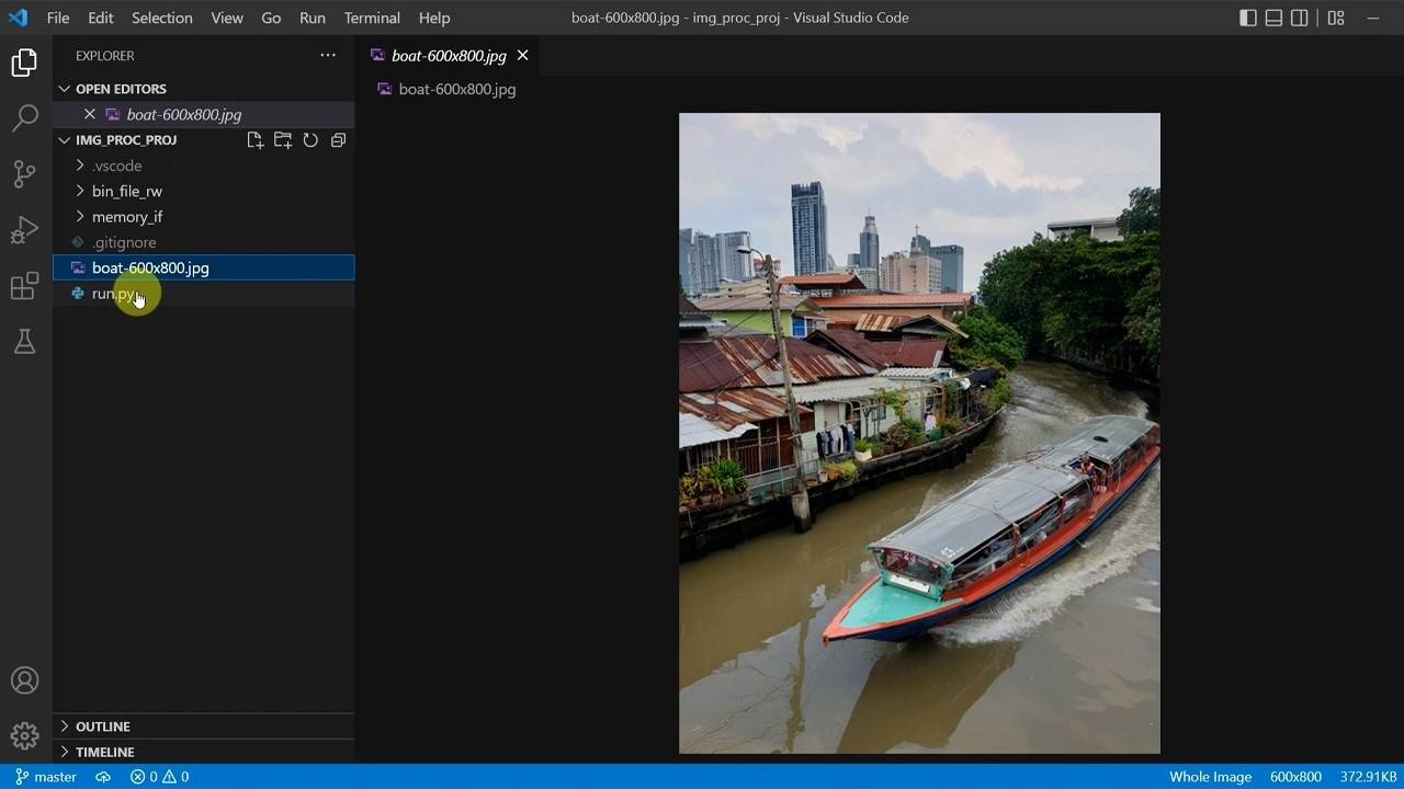
2 - Project starting point
Download the Zip file with the project starting point and get your development environment up and running.
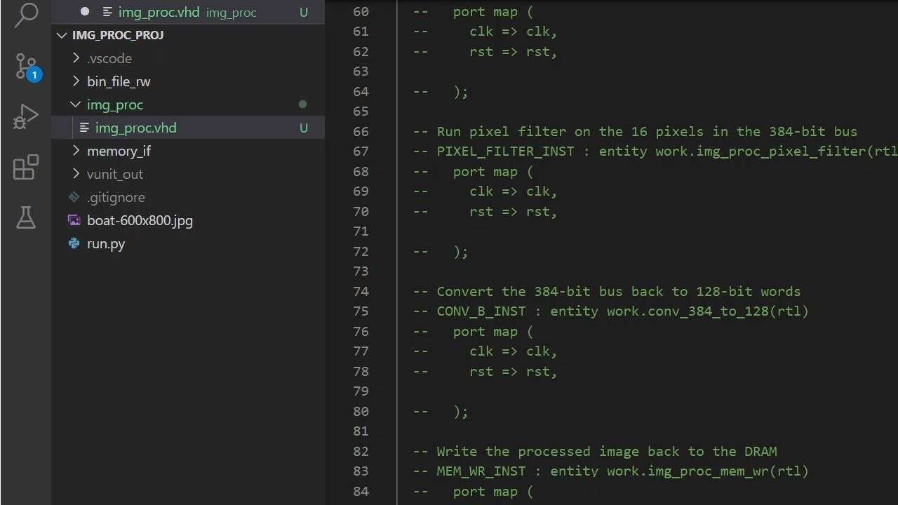
3 - What we will create
Let's create the img_proc structural module, define its entity and discuss the submodules it will contain.
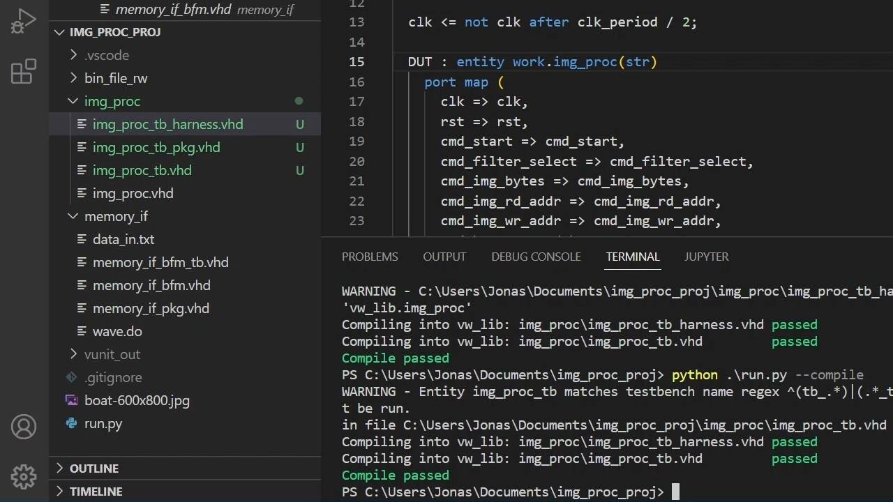
4 - Structuring the image processor TB
We will move parts of the main testbench into a package and a harness module to make it more manageable.
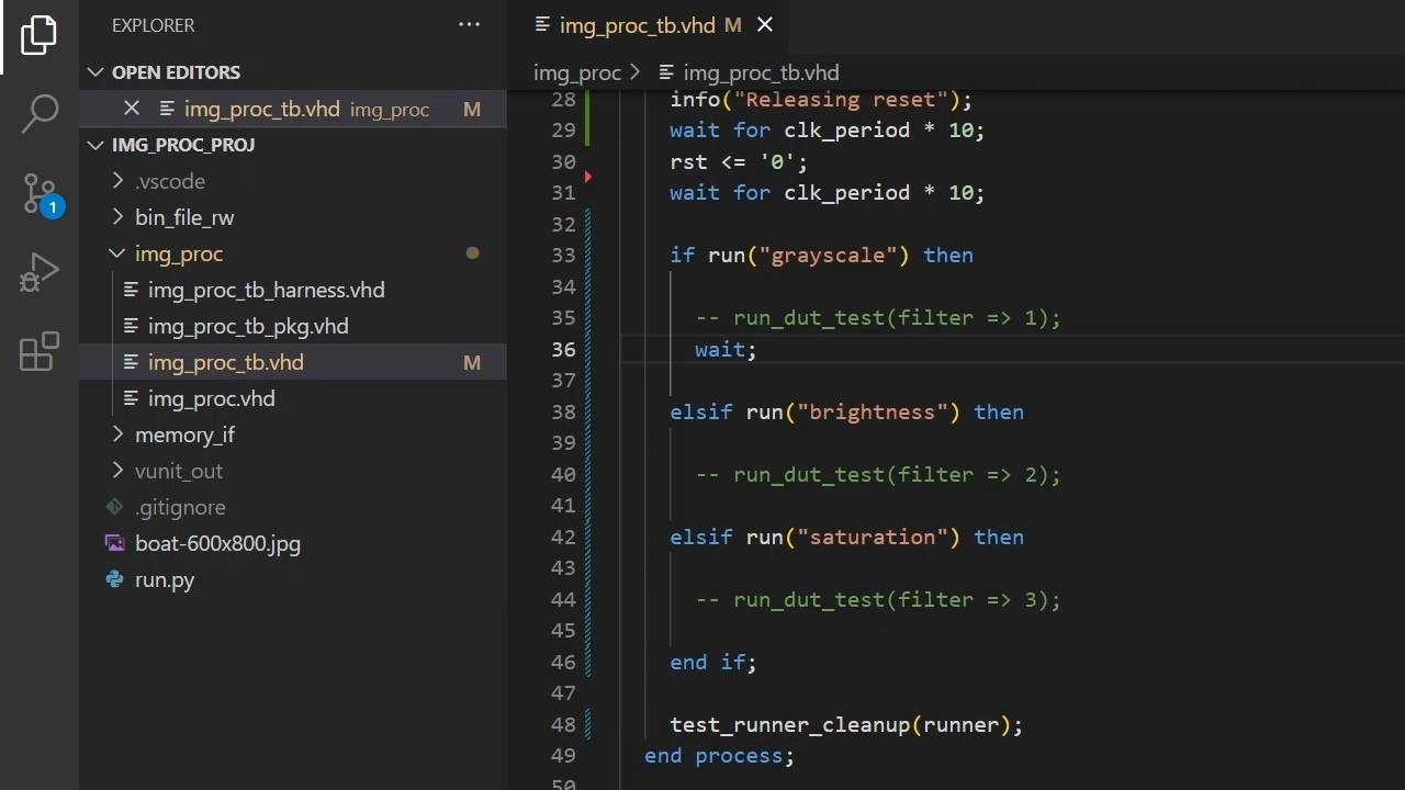
5 - Preparing the VUnit test cases
We will run our testbenches in this project through the VUnit VHDL verification framework.
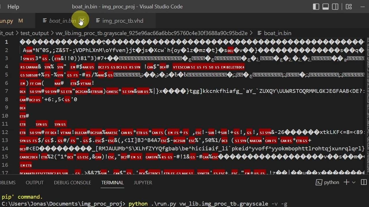
6 - Reading a JPG image into the VHDL TB
By using pre_config and post_check hooks from VUnit's Python library, we can convert the JPG image to and from a binary format.
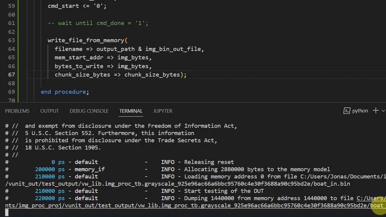
7 - Reusable test runner procedure
We will write a procedure within the sequencer process that we can reuse in each filter test case.
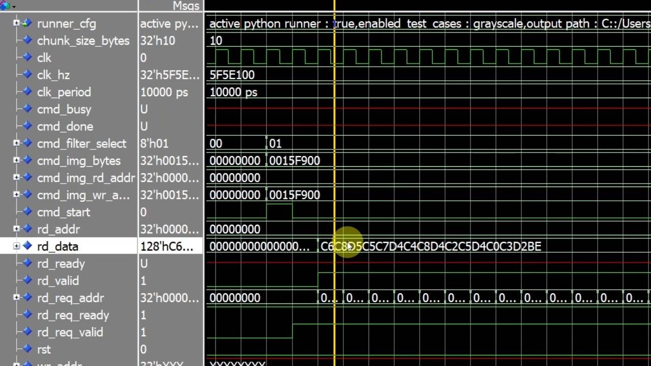
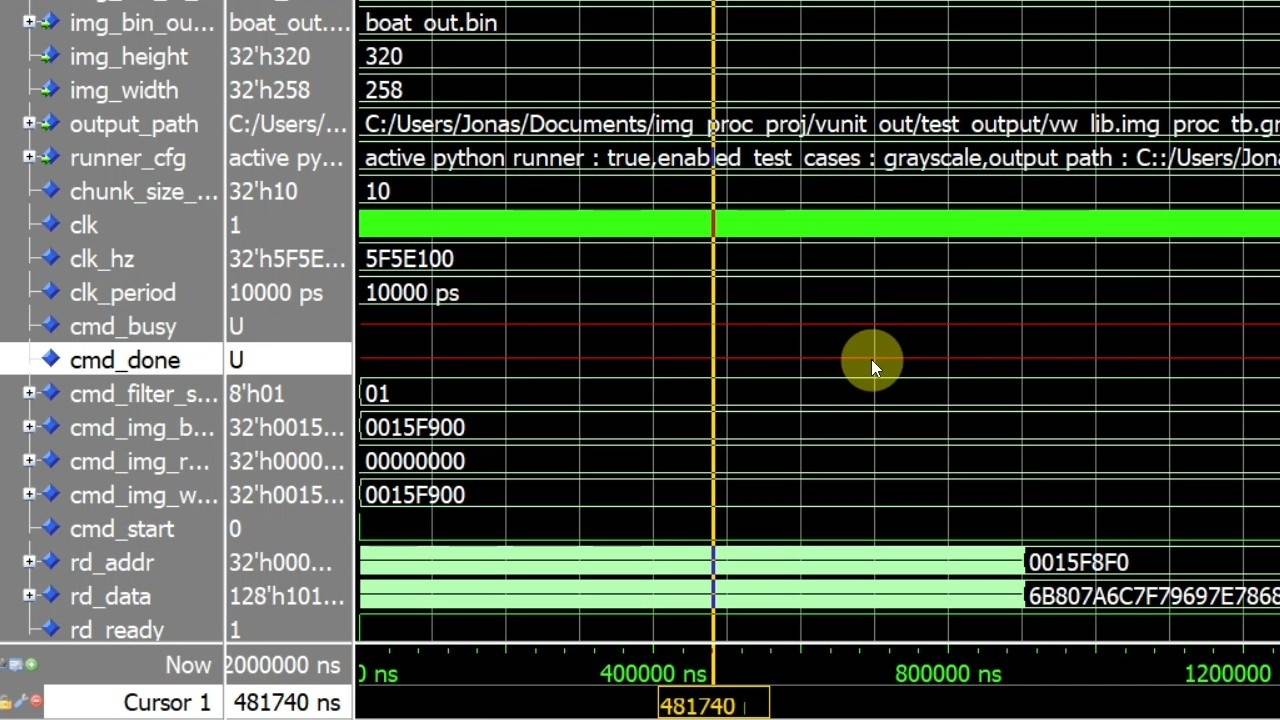
8 - Memory read request module
The first module we will implement is the memory read requester, which initiates the reading of data chunks from the DRAM interface.
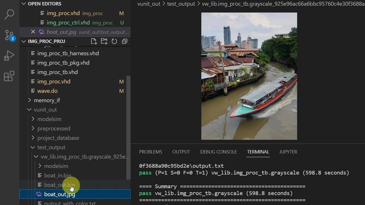
9 - Memory writer module
The memory writer module is responsible for setting the correct write address for each data chunk going back to the DRAM.
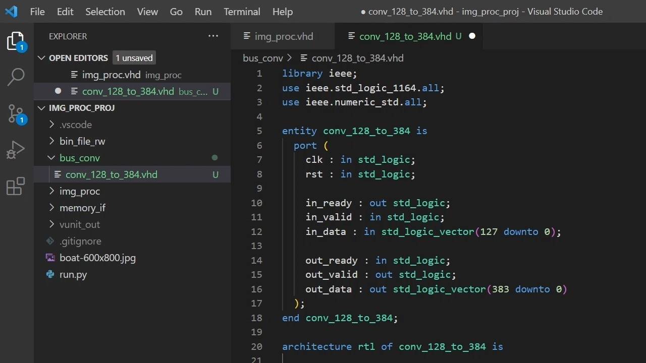
10 - Controller module
The controller is responsible for setting the busy and done outputs from the top image processor module.
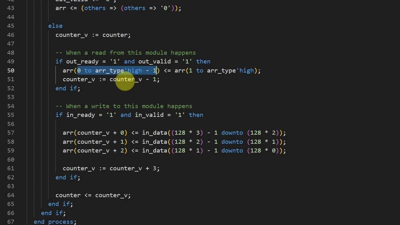
11 - Bus converter - narrow to wide
This module will collect three 16-byte data chunks and output them as three times wider 48-byte chunks.
12 - Bus converter - wide to narrow
We have to convert the 48-byte data chunks from the pixel filter back to 16-byte chunks that fit the DRAM interface.
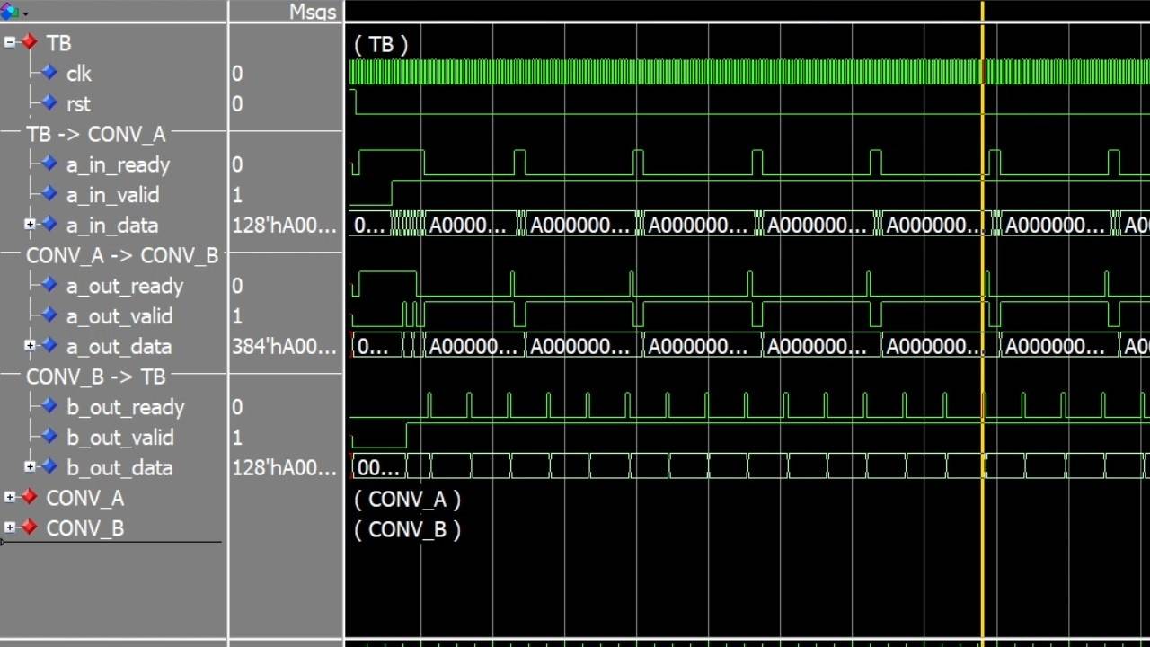
13 - Bus converter testbench
This self-checking testbench uses VUnit to verify both bus converter modules. Let me show you how it works!
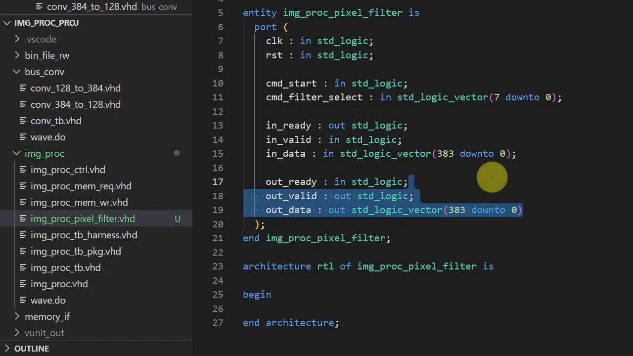
14 - Completing the top module
Let's define the pixel filter's entity so we can instantiate it to wrap up the top module.
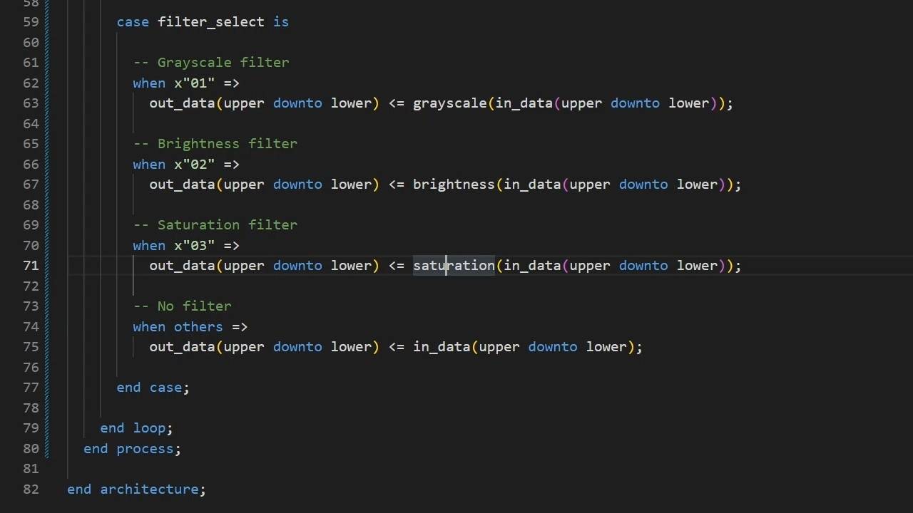
15 - Pixel filter module and package
It's finally time to implement the core functionality of our image processor module.
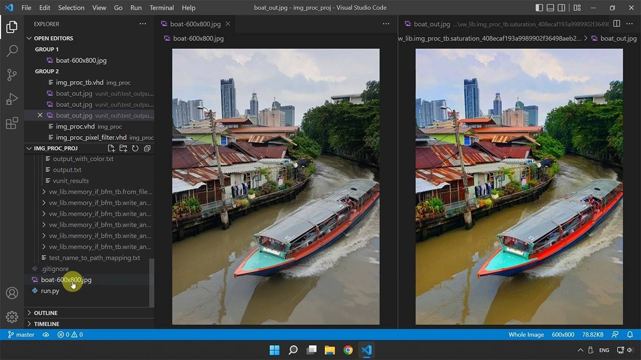
16 - Testing the complete system
Let's run the top testbench to see the filters in action! 😀



Reviews
There are no reviews yet.