Course: VGA Pong game on FPGA
$59
VHDL Pong game implementation course teaching how to control a VGA monitor from an FPGA, including sync signals, gameplay, and displaying images over VGA.
Description
This course teaches how to create a VHDL project with a VGA controller and several internal video sources. First, we’ll write the VHDL module that generates the VGA synchronization signals with correct timing characteristics.
Then, we move on to create two VHDL modules that produce two different test patterns. That’s to make sure that we completely understand how to manipulate any pixels on the screen using digital logic.
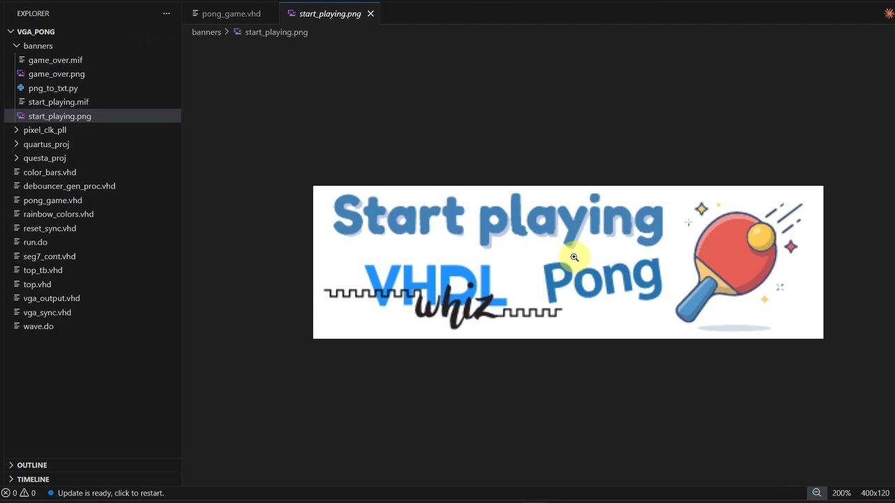
We’ll also see how to load an image into block RAM in the FPGA and display it on the VGA monitor. We’ll use those images as overlay banners on the Pong game to show the Welcome and Game Over screens.
Since the Pong game module is quite lengthy with all the gameplay features, we use AI to auto-generate most of it. But don’t worry, we go through the entire module afterward to understand how it works.
I’m doing this not only to save time, but because AI is here to stay. To be a successful FPGA engineer in the future, you need to embrace the new technology.
The problem with AI isn’t that people use it, but that they rely too much on it or don’t understand the code it creates. I’ll show you my best practices for using Claude and ChatGPT in VHDL projects.
Lots of fun and interesting learning points in this course, and I’m sure you’ll enjoy it!
This course is also available in the VHDLwhiz Membership.
The difference is that when you purchase this product, you get permanent access to the course, while the membership charges a monthly fee to access the content.
Hardware used in the course
I’m using the DE10-Lite board from Terasic, which has a VGA port. This board has an Altera MAX10 FPGA, so we’ll use the free version of the Altera Quartus software.
But many FPGA development boards have VGA ports. You can use a different board with a VGA output, or even an extension board like the Digilent Pmod VGA.
- Terasic DE10-Lite
Resellers: Terasic, Mouser, DigiKey
(Used in the course. You can use a different board with a VGA output.) - Digilent Pmod VGA (SKU: 410-345)
Resellers: Digilent, Farnell, Newark, Mouser, DigiKey
(VGA adapter for FPGA boards with no built-in VGA port.) - A monitor with a VGA input
(Or you can use an inexpensive VGA-to-HDMI adapter and connect your FPGA board to a TV or modern computer screen)
Software used in the course
I use Windows 11 in the course. All the other software is available for free for Windows and Linux:
- Quartus Prime Lite Edition
(Or the implementation software for your FPGA architecture) - Questa – Intel FPGA Edition (includes Starter Edition)
(Any version of ModelSim or QuestaSim will work) - Microsoft Visual Studio Code
(Any editor will do)
Course outline
The overview below shows the lessons in this course.

1 - Introduction
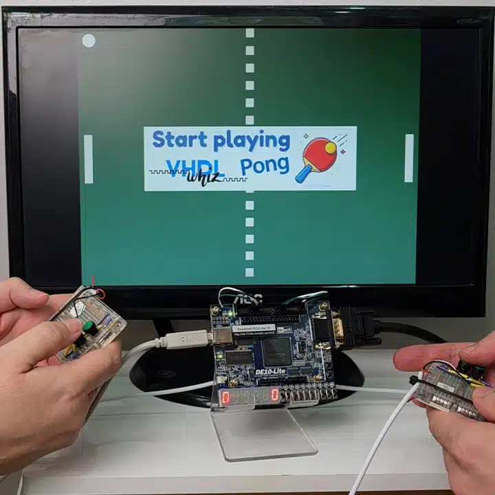
Pong is one of the oldest computer game concepts in the world. The first version appeared in 1972. Let me tell you about this FPGA implementation and why you will learn from this course.

2 - Getting started
I'm using the DE10-Lite board and this old VGA monitor, but there are many other options. Let's quick-start the Quartus VHDL project using Terasic's System Builder.
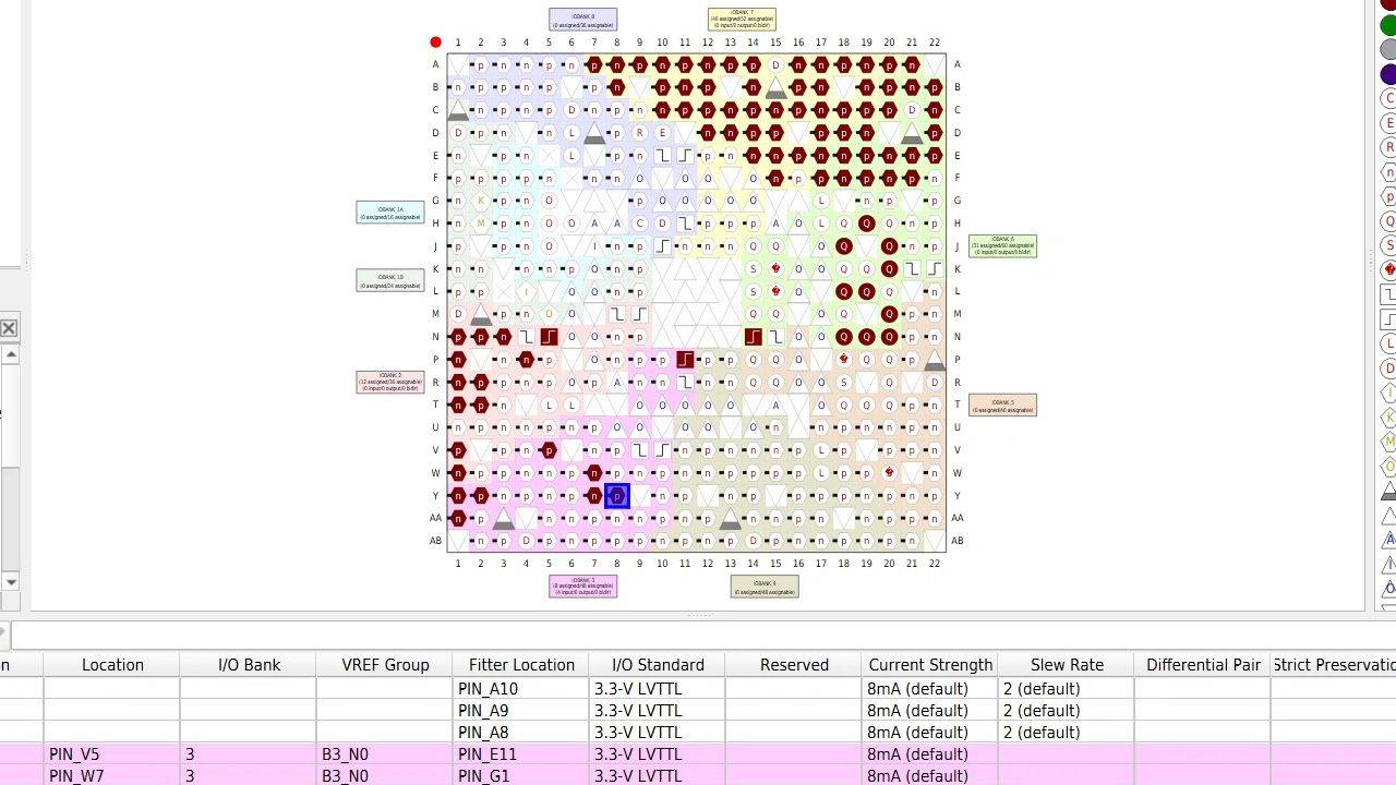
3 - Quartus project
Let's complete the pin constraints and make the necessary changes in the Altera Quartus Lite FPGA implementation tool. We'll also need a PLL to generate the 25.175 MHz VGA clock.
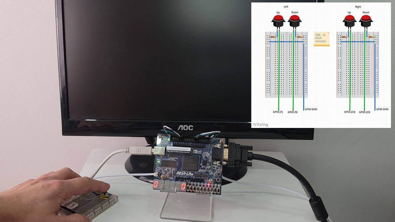
4 - Top module peripherals
In this lesson, we'll start on the Top module by instantiating the PLL to generate the clock, a reset synchronizer, switch debouncers, and a VHDL module to control the 7-segment display digits.
5 - Top-level testbench
Let's create a VHDL testbench to verify the timing of the VGA synchronization signals. We'll also define the entity for the vga_sync module.
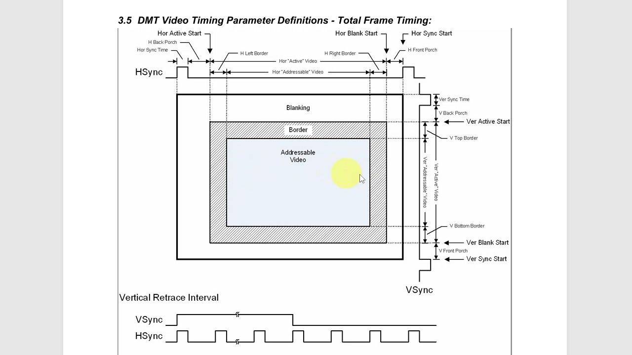
6 - VGA synchronization module
Implement the vga_sync VHDL module with horizontal and vertical counters to generate the hsync and vsync timing signals. We verify the pulse widths in simulation, then test on the monitor.
7 - VGA source selector
This module will multiplex between three different VGA video sources. It shall also register (add flip-flops to) the output signals to reduce the skew between them.
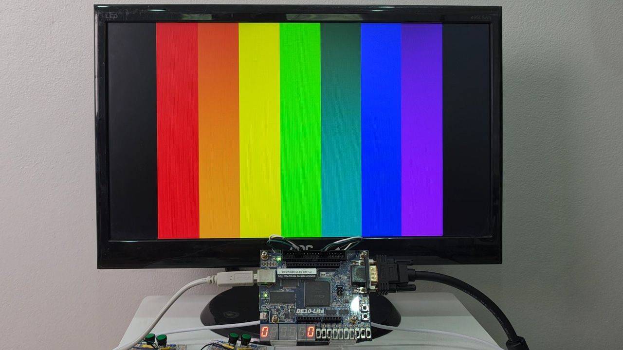
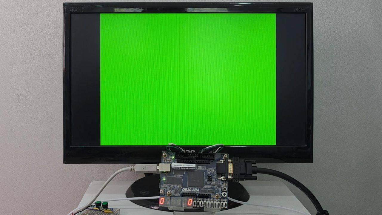
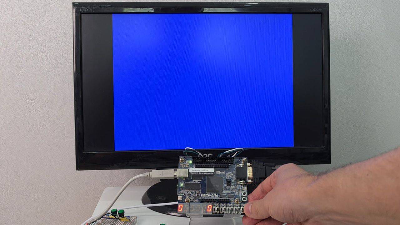
8 - VGA test patterns
We create two simple VGA test pattern modules: horizontal color bars and vertical rainbow bands to help us understand how to use the column and row pixel addresses to show images on the monitor.

9 - Pong game module and state machine
Time to start on the Pong game module! We'll define the entity, instantiate it in the top module, and create a main finite-state machine (FSM). But we'll outsource the rest to AI.
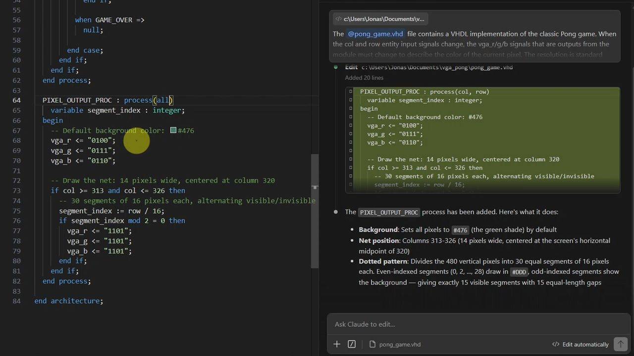
10 - Pong game graphics
We'll use AI tools to generate the logic for drawing the ping-pong board on the VGA monitor. I'll show you how I prompt Claude and ChatGPT to produce usable VHDL code.

11 - Pong gameplay
Let's walk through the AI-generated code to understand how it works: ball movement, paddle control, game physics, scoring, and game speed. Then we test the Pong game on the FPGA!
12 - Banner ROM
We create a block RAM module to store banner images for the Start and Game Over screens. A Python script converts PNG files to Altera's MIF format for memory initialization at compile time.
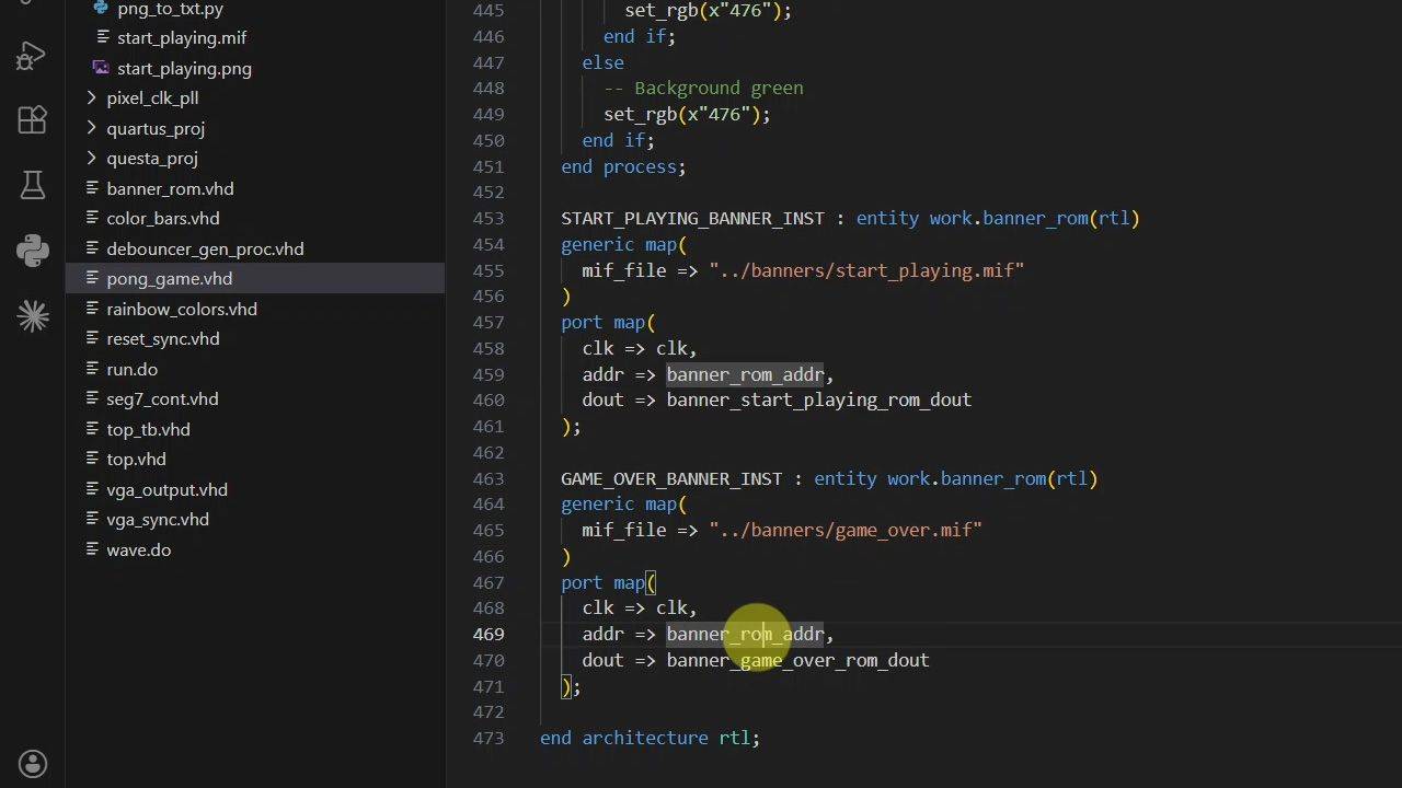
13 - Banner overlays
Since the pixel data is now stored in block RAM on the Altera MAX10 FPGA, we can modify the VGA output process to overlay them as banners on the screen based on the Pong game FSM state.
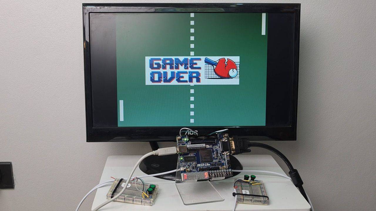
14 - Playing the game
Enjoy this gameplay video from the hardware implementation of the Pong game we created! Who will win the FPGA Pong cup?
This course is also available in the VHDLwhiz Membership.
The difference is that when you purchase this product, you get permanent access to the course, while the membership charges a monthly fee to access the content.

Reviews
There are no reviews yet.