Course: Bluetooth FPGA control via mobile app
Add Bluetooth connectivity to FPGA projects! Learn to control the color LEDs on your board from a phone and show VHDL signal values in the mobile app.
Description
Learn to make an FPGA-powered Bluetooth gadget with this course. We’ll create a demo VHDL project that allows you to control the color and illumination intensity of LEDs on the FPGA board with a mobile app.
I will also show how to send tagged FPGA signal values in the opposite direction, from the FPGA to the phone. And we’ll implement pairing mode that allows a new phone to bond (exchange cryptographic keys) with the Bluetooth chip.
You’ll learn about advanced VHDL state machines, pattern matching, text parsing, timers, and how to create a self-checking testbench that precisely simulates the UART communication with the BLE transceiver.
The same methods are applicable for interfacing with other AT command set (ASCII command-based) devices that communicate with the host MCU, or FPGA in this case, over UART, including Wi-Fi modules like the ESP32.
See the video below for a preview of selected lessons.
This course is only available in the VHDLwhiz Membership.
The membership subscription gives you access to this and many other courses and VHDL resources.
You pay monthly to access the membership and can cancel the automatic renewal anytime. There is no lock-in period or hidden fees.
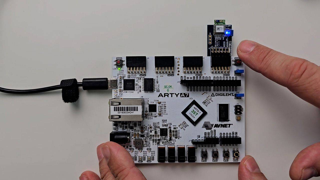
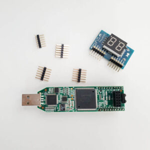
In this course, I use the Digilent Pmod BLE (Bluetooth Low Energy ) module with the Microchip RN4871 transceiver and the Arty A7-35T FPGA board.
I also provide constraint files for the Arty S7-50 board. But you can use almost any FPGA board, and if it has a Pmod connector, no wires are needed.
Hardware used in the course
- Pmod BLE: Bluetooth Low Energy module (SKU: 410-359)
Resellers: Digilent, DigiKey, Newark, Mouser, Farnell (UK), RS Electronics UK - Arty S7-50: Xilinx Spartan-7 FPGA (SKU: 410-352)
Resellers: Digilent, Farnell, Newark, Mouser, DigiKey
(You can use almost any board) - A smartphone
(Android mobile used in course but iPhone works too)
Software used in the course
I am using Windows 11 in the course. All the other software is available for free for Windows and Linux:
- Questa – Intel FPGA Edition(includes Starter Edition)
(Any version of ModelSim or QuestaSim will work) - AMD Vivado
(Or the implementation software for your FPGA architecture) - Microsoft Visual Studio Code
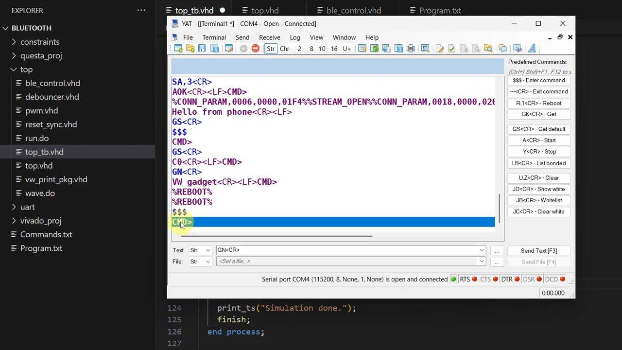
(Any editor will do) - YAT – Yet Another Terminal
(Any serial (UART) terminal program will do) - Serial Bluetooth Terminal – Google Play (Android)
(Android phone used in course; similar app on the Apple Store for iPhone)
Course outline
The overview below shows the lessons in this course.

1 - Introduction
Welcome to the course! Let's talk about what we will create and what you can learn.
3 - Top module and first communication with the BLE module
To establish initial communication with the Microchip RN4871 Bluetooth chip, we'll create a preliminary top-level VHDL module that forwards the UART signals to the computer.
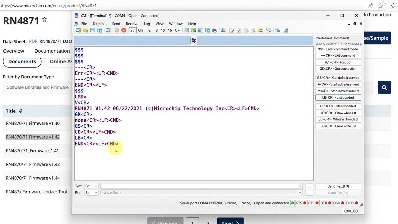
4 - Firmware update
Let's go through some basic ASCII commands and upgrade the RN4871 chip's firmware.
5 - RN4870/71 BLE module commands
Let's derive a "program" or list of commands to use as factory settings, to enter pairing mode, and to enter normal Bluetooth gadget operation.
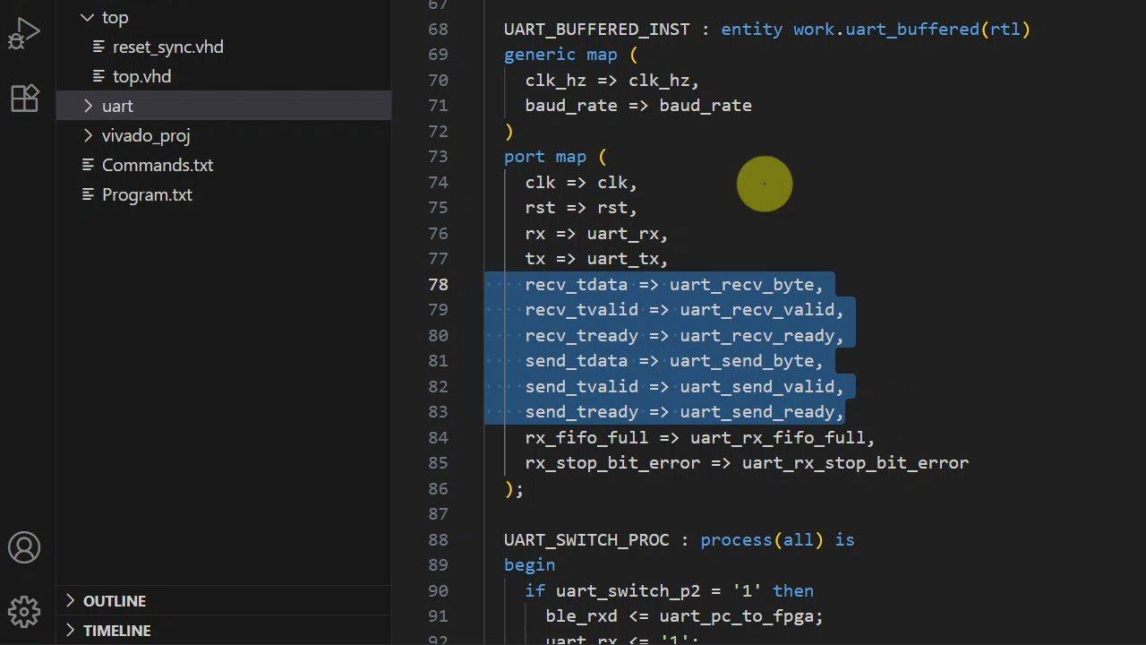
6 - UART module and top-level entity
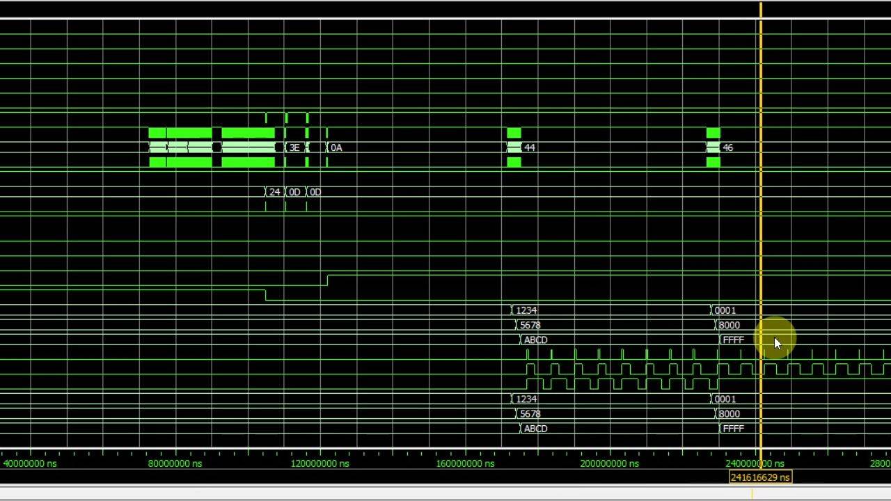
We'll use the UART buffered module from the VHDLwhiz resource library to implement the serial communication with the BLE chip. Let's also get the UART bus functional model (BFM) for the testbench.
7 - PWM and debouncer modules
We can get a switch debouncer and pulse width modulation (PWM) module from the VHDLwhiz Membership resource library. We need them to interface with peripherals.
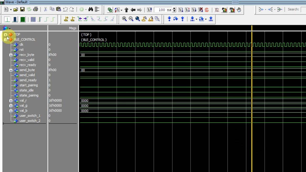
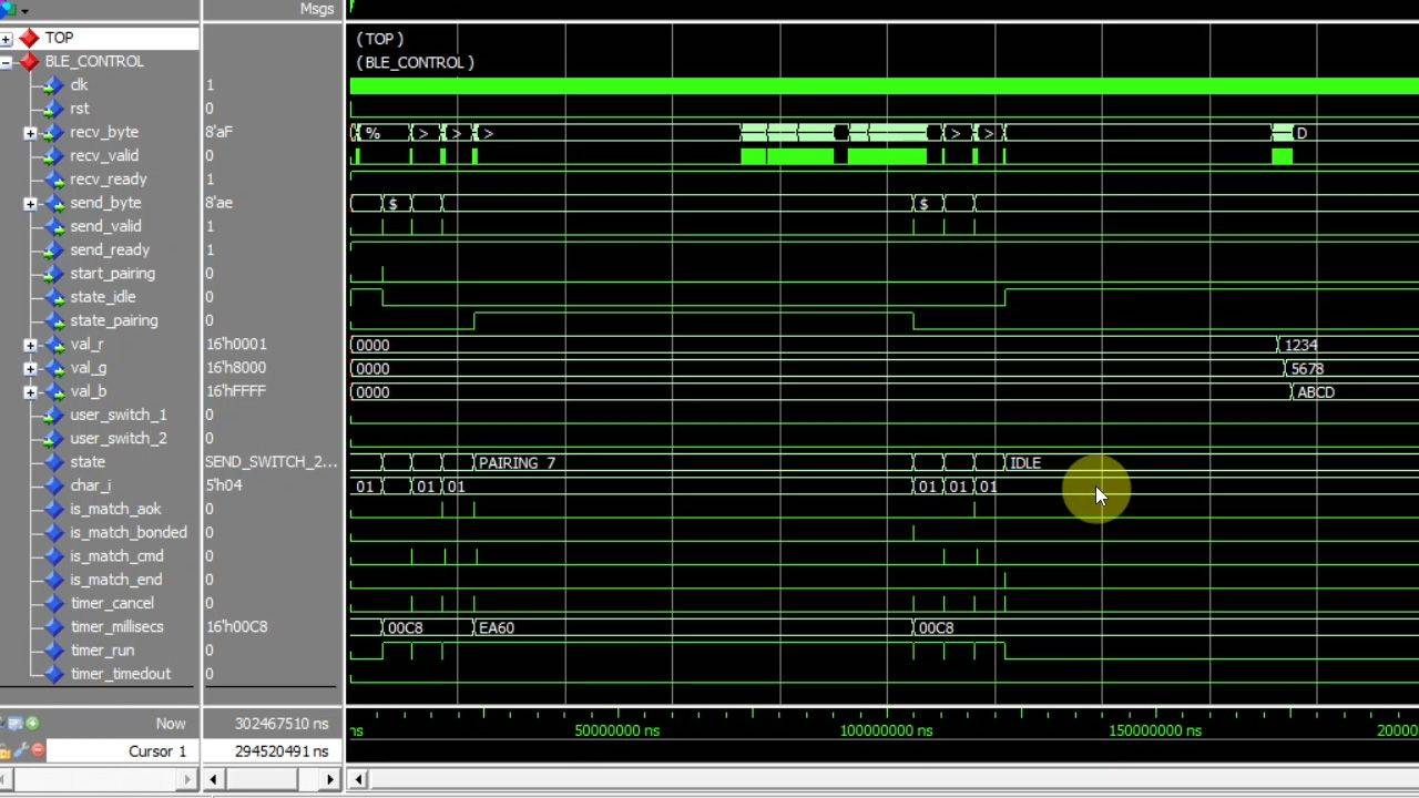
8 - BLE controller module and top-level testbench
Let's start on the Bluetooth controller VHDL module that will contain the finite state machine that shall interact with the BLE device.
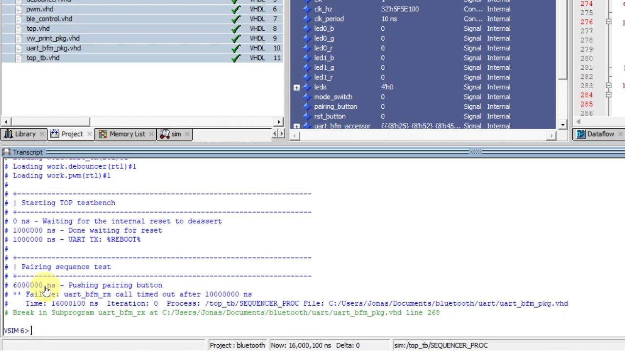
9 - Top-level testbench UART BFM
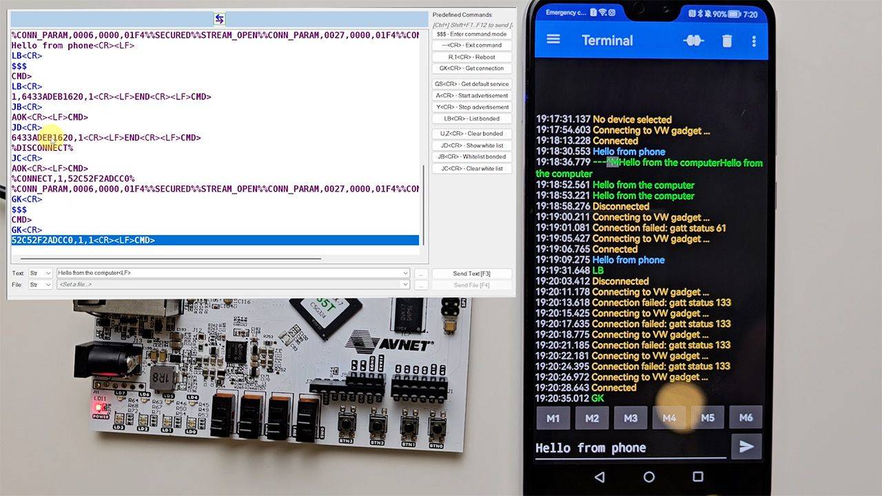
See how to send ASCII strings over UART in the VHDL testbench while reading and checking the responses from the device under test (DUT).
10 - Send UART message VHDL procedure
Finally, we'll start implementing the finite state machine (FSM) in the Bluetooth controller module that will communicate with the RN4871 chip.
11 - Pattern match module
We'll use multiple pattern-matching VHDL modules to continuously monitor the bytes that arrive from the Bluetooth chip, looking for predefined tag strings.
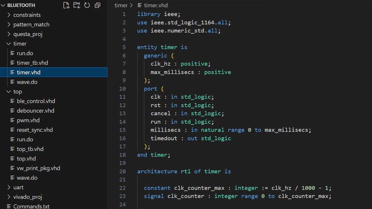
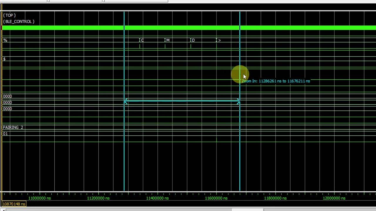
12 - Timer module
To stay in pairing mode for a maximum of 60 seconds, we need a timer. We'll also use this VHDL stop watch implementation to avoid waiting for status messages indefinitely.
13 - Procedure to wait for UART reply
Interacting with the Bluetooth chip over UART requires waiting for status messages or command replies. We'll make a VHDL procedure to handle that in our FSM.
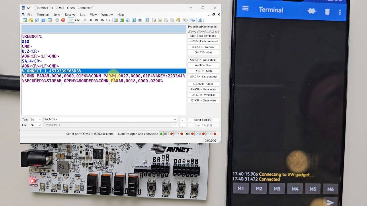
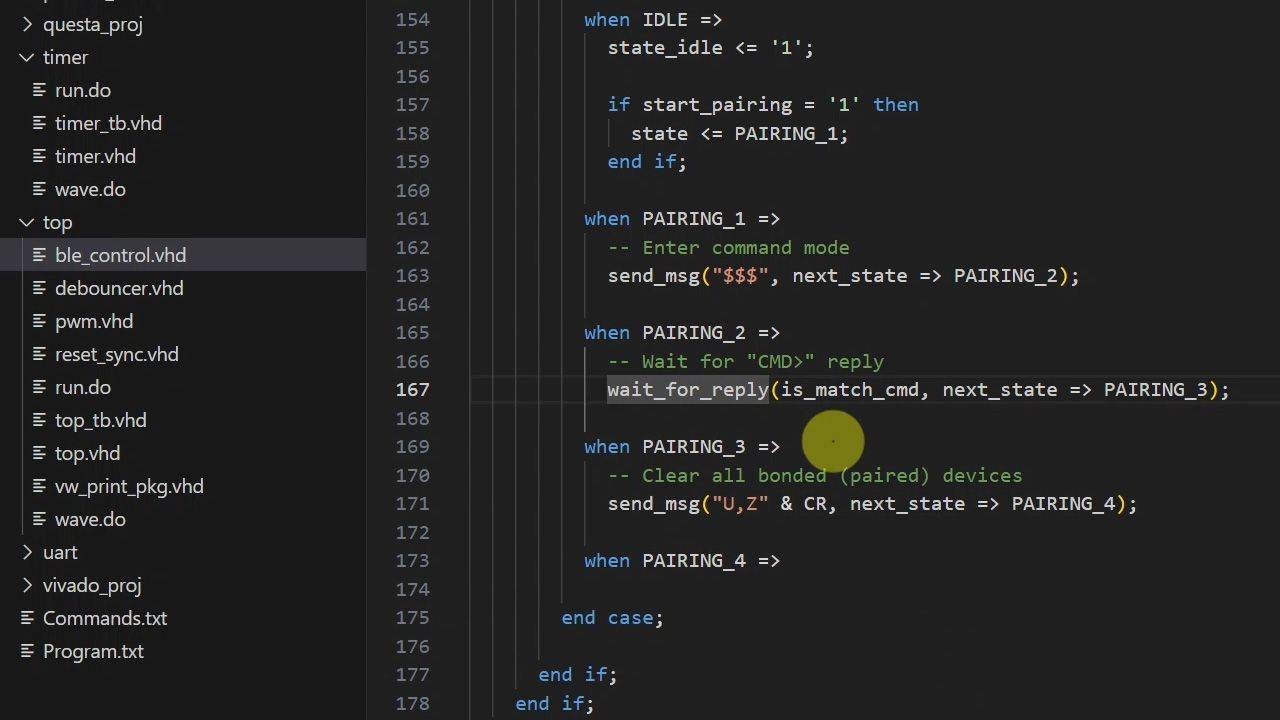
14 - Bluetooth pairing sequence
Let's implement the rest of the Bluetooth pairing sequence by using our send message and wait for reply VHDL procedures.
15 - Value reader Bluetooth messages parser module
To pass VHDL signal values to the FPGA over Bluetooth, we'll send them as ASCII hex characters and prefix them with known text string tags.
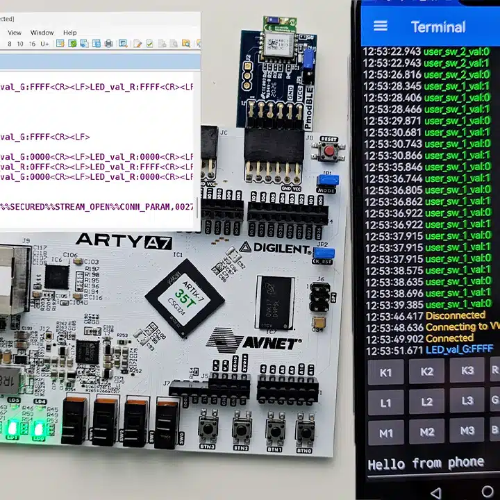
16 - Transmitting user switch values over Bluetooth
It's also possible to pass VHDL signal values from the FPGA to the mobile app over Bluetooth. We'll use two toggle switches on the board for this demo.
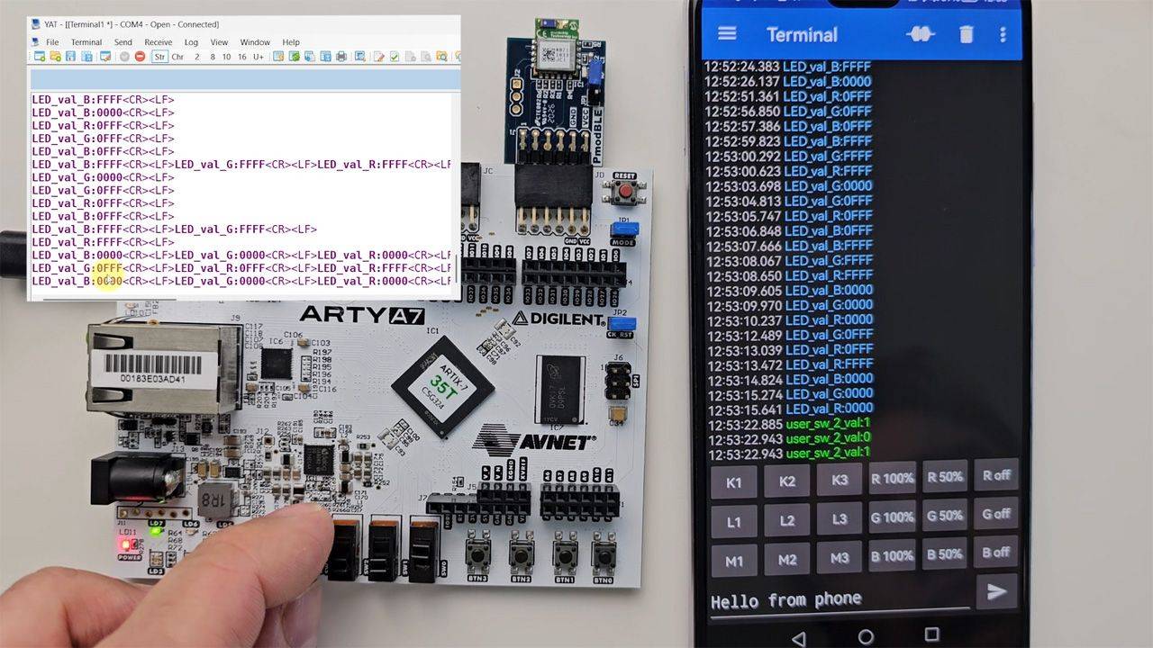
17 - FPGA board and Bluetooth mobile app design test
Get ready to be amazed! If everything goes well, we'll be interacting with the FPGA from our mobile phone app over Bluetooth.
This course is only available in the VHDLwhiz Membership.
The membership subscription gives you access to this and many other courses and VHDL resources.
You pay monthly to access the membership and can cancel the automatic renewal anytime. There is no lock-in period or hidden fees.
Reviews
There are no reviews yet.