Course: I²C controller for interfacing a real-time clock/calendar module in VHDL
$59
Learn to create an I²C controller (master) in VHDL and communicate with the Digilent Pmod RTCC: Real-time Clock / Calendar module.
Description
This course teaches how to create an I²C controller (master) in VHDL and implement it on an FPGA board.
Unlike other I²C controllers, this implementation uses a generic command interface, making it easy to use in various VHDL projects. Furthermore, we’ll use the AXI-style ready/valid handshake for the write and read buses so that you can add the module to a block design in Vivado.
We’ll target the Pmod RTCC: Real-time Clock / Calendar module from Digilent to have a meaningful example project for testing in the lab. Then we’ll use the I²C controller to communicate the Microchip MCP79410 I²C target (slave) on the Pmod RTCC.
The battery-powered RTCC module is great for adding a persistent timekeeping device to your FPGA projects, but the I²C controller isn’t limited to that device. You can use this method for interfacing most I²C-enabled chips.
I’m using a Python script to set and read the time and date values from the RTCC module. The script and all the code you need are available in the course.
This course is also available in the VHDLwhiz Membership.
The difference is that when you purchase this product, you get permanent access to the course, while the membership charges a monthly fee to access the content.
Hardware used in the course
- Digilent Pmod RTCC: Real-time Clock / Calendar (SKU: 410-218)
Resellers: Digilent, Farnell, Newark, Mouser, Digi-Key
(You can use a different I²C target if you want, but then you have to study the datasheet to find the address of the device and which registers you can access.) - Arty S7-50: Xilinx Spartan-7 FPGA (SKU: 410-352)
Resellers: Digilent, Farnell, Newark, Mouser, Digi-Key
(You can use almost any board that has UART, with or without a Pmod connector. If it doesn’t have a Pmod connector, you can always use regular IO pins. But you’ll have to modify the constraints (XDC) file if you use a different board.)
Search for SKU numbers “410-218” and “410-352” in your favorite online electronics store or e-commerce sites like eBay to find them.
Software used in the course
I am using Windows 11 in the course. All the other software is available for free for Windows and Linux:
- Questa – Intel FPGA Edition(includes Starter Edition)
(Any version of ModelSim or QuestaSim will work) - Xilinx Vivado
(Or the implementation software for your FPGA architecture) - Microsoft Visual Studio Code
(Any editor will do)
Course outline
The overview below shows the lessons you can access after purchasing this course.
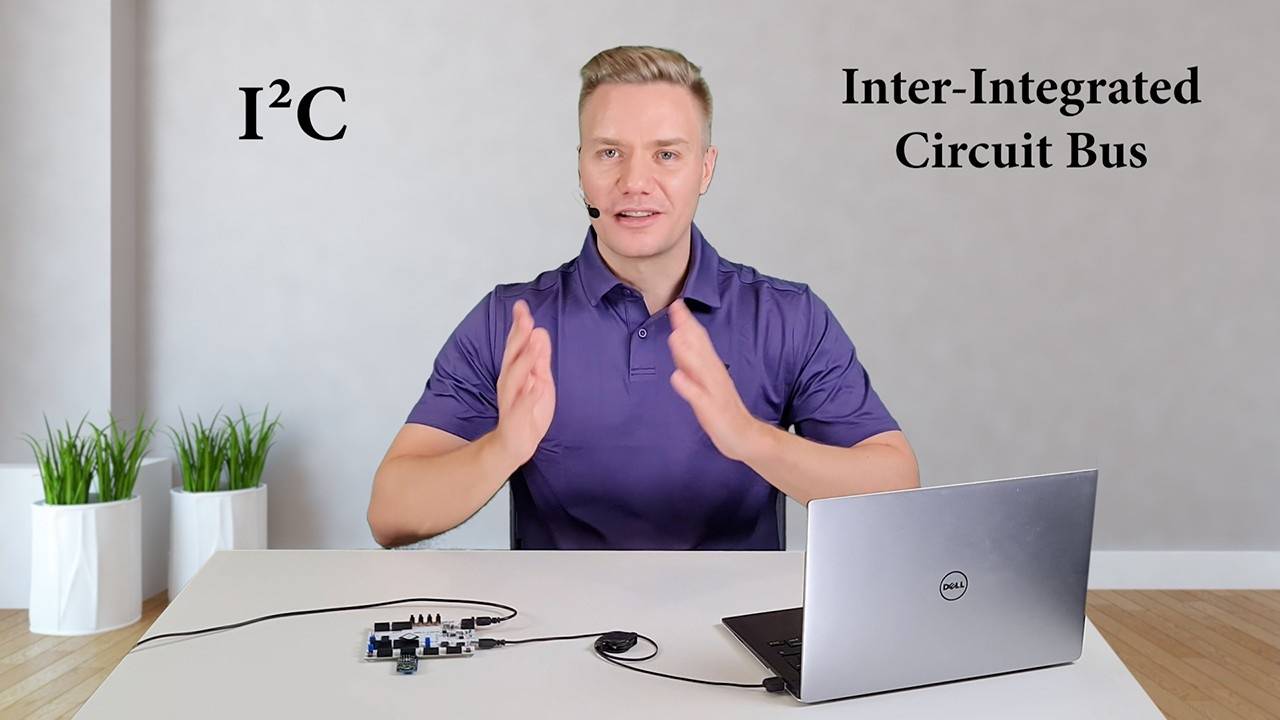
1 - About I²C and what we will create
I²C is one of the most used data buses for interfacing peripheral devices and microchips.
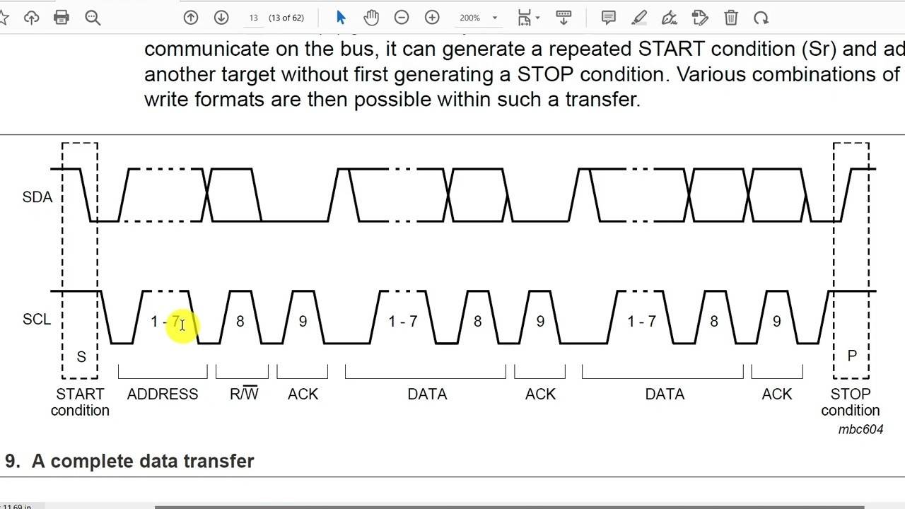
2 - How I²C works
Check out the I2C-bus specification and user manual to see how this communication protocol works.
3 - Design overview
We need to understand what we are going to create before we start coding.
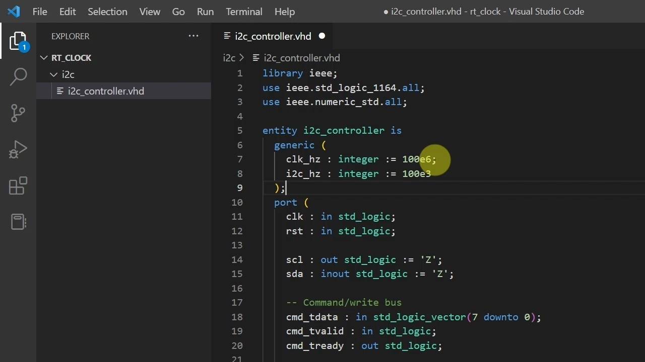
4 - Project setup
We'll start by defining the entity, instantiating it in a testbench, and creating a Questa project.
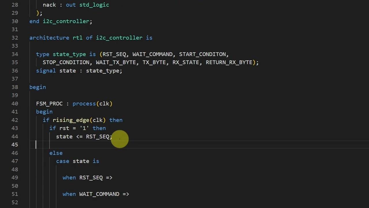
5 - Defining the FSM states
The next step is defining the finite-state machine (FSM) that will govern our new module.
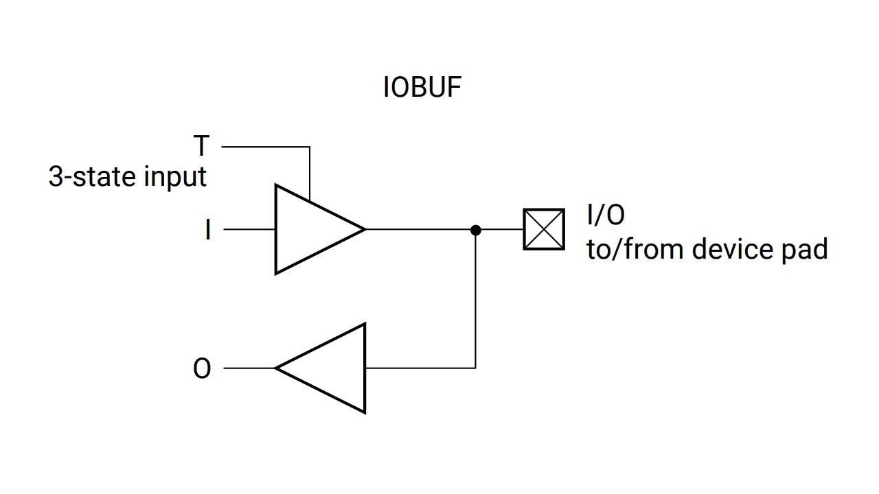
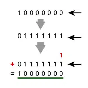
6 - How to implement and simulate tri-state logic.
We'll describe the tri-state buffers using VHDL to infer IOBUF primitives in the FPGA.
7 - Bus reset sequence
By toggling SCL several times without pulling SDA low, we may be able to reset I²C targets that are in an undesirable state.
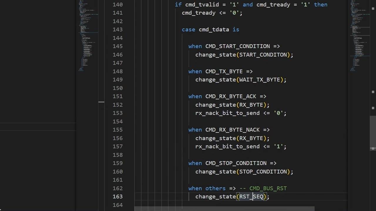
8 - Command processing
We'll tell the I²C controller what to do through our custom command interface.
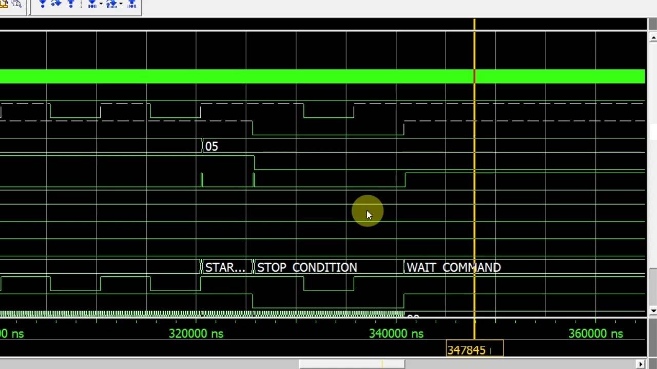
9 - Start and stop conditions
Start and stop conditions mark the beginning and end of a transfer sequence.
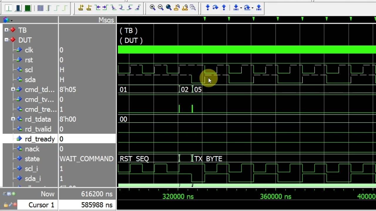
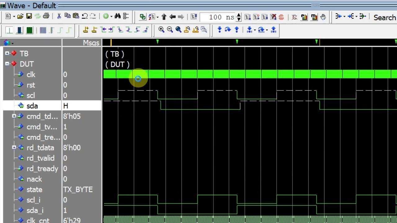
10 - Sending bytes
Send a byte and sample the ACK response from the target.
11 - Delaying the SDA output
We must slightly delay SDA with respect to SCL to avoid causing unintentional start and stop conditions.
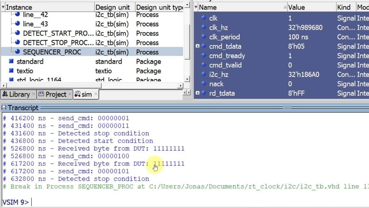
12 - Receiving bytes
Receive a byte by sampling SDA and follow up with an ACK or NACK from the controller.
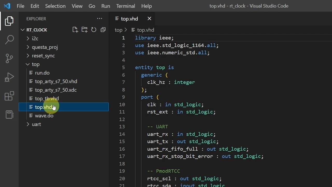
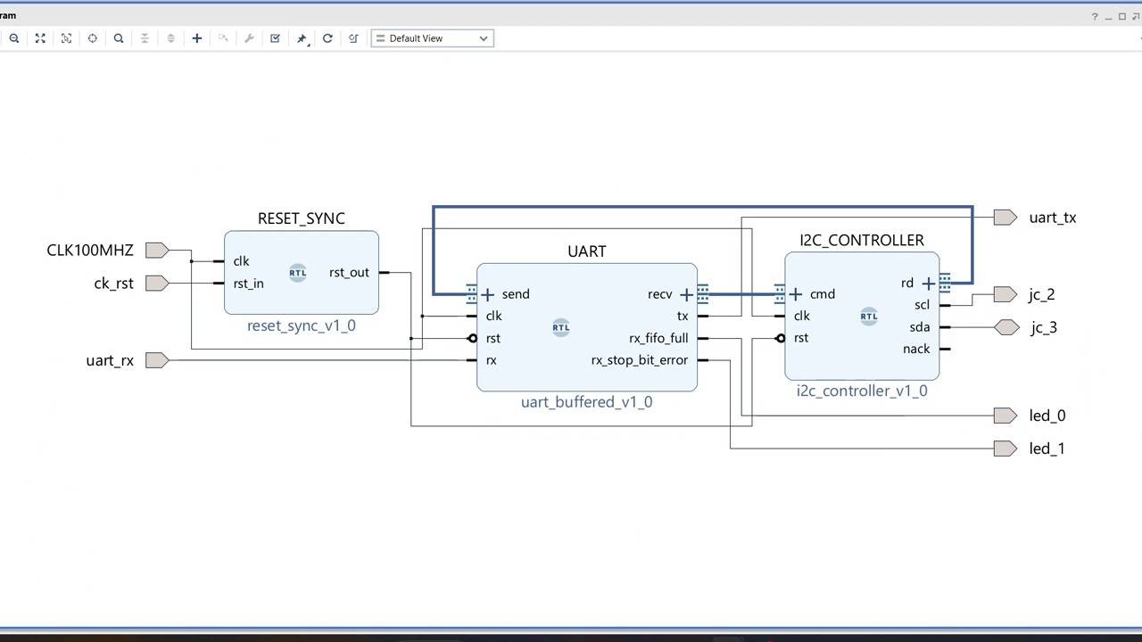
13 - Top module with UART communication
Let's create a top-level VHDL module with UART functionality to test the design on an FPGA board.
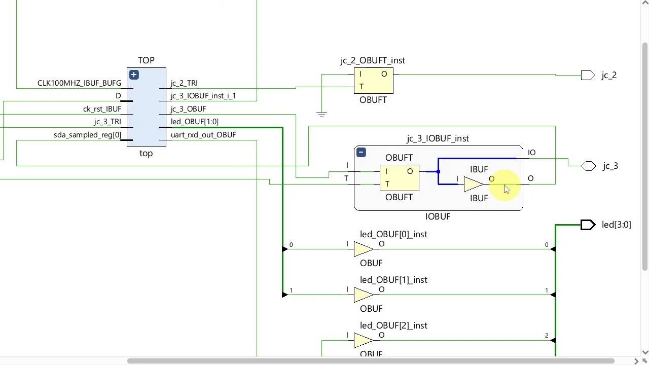
14 - Implementing the design in Vivado
I'm using an Arty S7-50 board from Digilent, but the design should work on almost any FPGA.
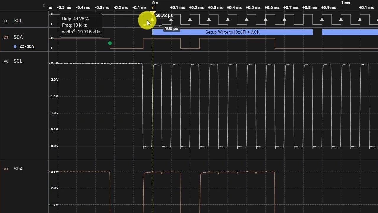
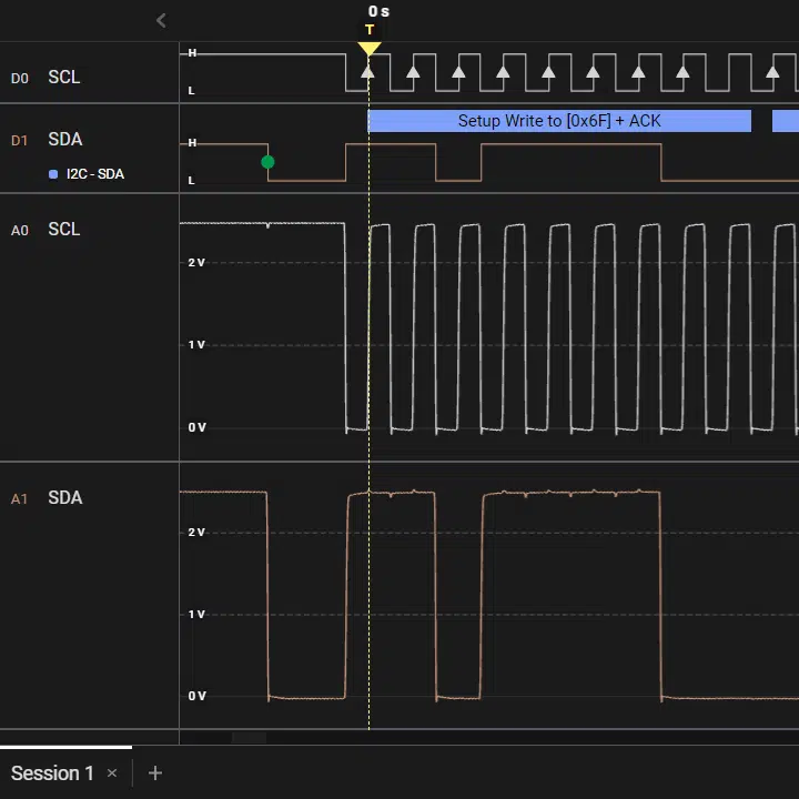
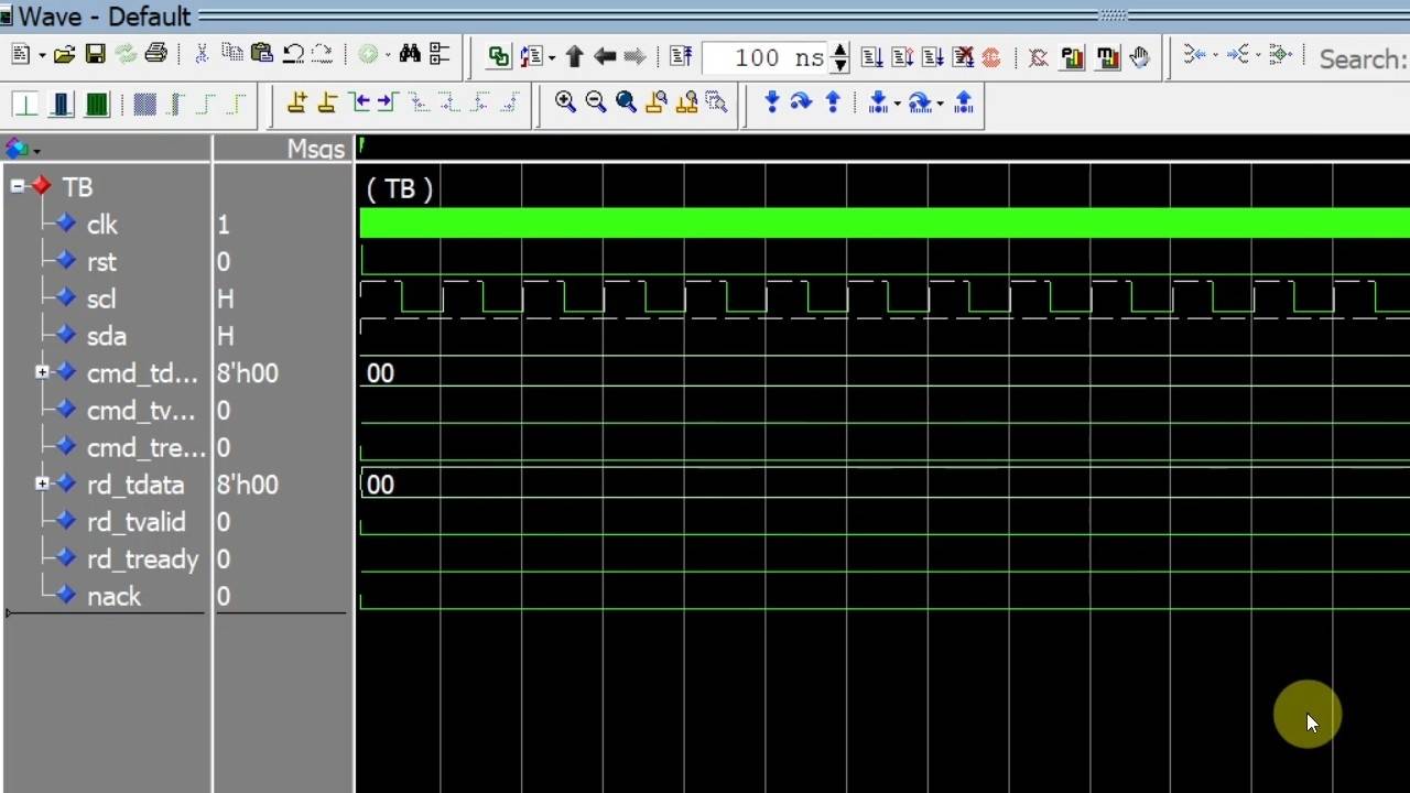
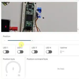
15 - Lab testing
Let's try communicating with the board using a serial terminal.
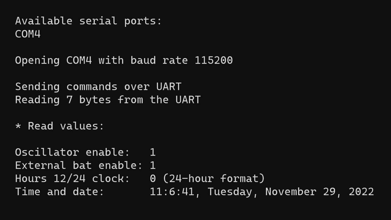
16 - Setting and reading the time and date
We'll use a Python script to set and read the time and date in a human-readable format.

Reviews
There are no reviews yet.