Course: Pmod OLED controller: Display text and graphics with an FPGA
Connect an LED panel to your FPGA design to show messages or images. See how to read pixel data from a file into block RAM using VHDL.
Description
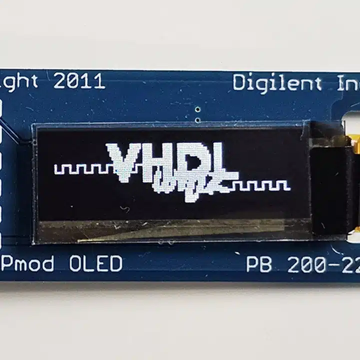
This course teaches how to add a screen to an FPGA board. The Pmod OLED module from Digilent is a tiny 128×32 pixel LED display that can show text or graphics. But to use it, you must initialize it using the SPI interface.
We’ll solve that by writing an SPI master and an OLED controller module that will set up the display on power-up and continuously redraw the image on the screen.
Furthermore, you’ll learn to read images from a file using VHDL and store them in block RAM on the FPGA. Then, we’ll make a demo design that can switch between four pages of images and text.
Not only does this course teach how to use this display and the SPI interface, but also how to simplify complicated state machines with clever use of VHDL procedures.
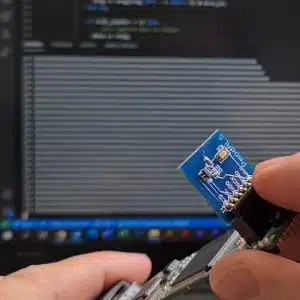
I’m using the Arty S7-50 board from Digilent with a Xilinx Spartan-7 FPGA, but you can use almost any board for this project. If it has a Pmod connector, you can plug the display directly into your development board. If not, you can use jumper wires to connect the board to generic IO pins and the 3.3V power.
This course is only available in the VHDLwhiz Membership.
The membership subscription gives you access to this and many other courses and VHDL resources.
You pay monthly to access the membership and can cancel the automatic renewal anytime. There is no lock-in period or hidden fees.
Hardware used in the course
- Pmod OLED: 128 x 32 Pixel Monochromatic OLED Display (SKU: 410-222)
Resellers: Digilent, Farnell, Newark, DigiKey, Mouser, RS Electronics - Arty S7-50: Xilinx Spartan-7 FPGA (SKU: 410-352)
Resellers: Digilent, Farnell, Newark, Mouser, DigiKey
(You can use almost any FPGA board.)
Software used in the course
I am using Windows 11 in the course. All the other software is available for free for Windows and Linux:
- Questa – Intel FPGA Edition(includes Starter Edition)
(Any version of ModelSim or QuestaSim will work) - Xilinx Vivado
(Or the implementation software for your FPGA architecture) - Microsoft Visual Studio Code
(Any editor will do)
Course outline
The overview below shows the lessons in this course.

1 - Introduction
Welcome to the course! This is what we'll do.

2 - About interfacing the display
Let me show you how the display works and where you can find the relevant information in the datasheets.

3 - SPI TX module outline
The SSD1306 OLED display controller uses the Serial Peripheral Interface (SPI) for command and data transfer. We'll create an SPI transmitter for that.

4 - SPI TX testbench
Let's create a manual-check testbench before we implement the actual RTL module.

5 - SPI TX declarations
We'll start on the SPI transmitter VHDL module by declaring constants, types, and signals to use in the finite-state machine (FSM).

6 - SPI TX finite-state machine
The finite-state machine process will transmit bits over the SPI interface while upholding the timing requirements.

7 - Top module outline
The top VHDL module will only contain instances of other modules and signals to interconnect them, but no logic.

8 - Top testbench
Let's create a testbench for the top module so we can simulate while developing the rest of the project.

9 - OLED controller module outline
In this lesson, we'll define the entity for the main controller module and instantiate it in the top-level testbench.

10 - OLED controller configuration bytes
We must send many command bytes to initialize the display's operation mode before using it. Let's conveniently store them in a VHDL array.

11 - OLED controller FSM outline
Let's start on the finite-state machine (FSM) in the OLED controller module by defining its type, signal, and state names.

12 - OLED controller FSM subprograms
In the FSM process, we'll define two helper procedures to make the state machine code more readable and avoid repeating code.

13 - OLED controller FSM implementation
We've already done most of the work in the OLED controller module. We just need to fill in the blanks to complete the finite-state machine.

14 - Top Arty S7 board wrapper
You can make a wrapper for the top-level VHDL module to customize it for almost any FPGA board.

15 - Experimenting with page and pixel addressing
Let's write some temporary code in the top module to see that we can control the display and activate specific pixels.

16 - Frame buffer in block RAM for storing pixel data
We'll use one block RAM primitive in this Xilinx FPGA to store four 128x32-bit images for showing on the display.

17 - Loading an image file into the block RAM
Use an impure function in VHDL to load initial values from a TXT ASCII art file into block RAM on the FPGA.

18 - Switching between images
Finally, we'll create a frame selector module to switch between the images in the RAM when we flick switches on the FPGA board.
This course is only available in the VHDLwhiz Membership.
The membership subscription gives you access to this and many other courses and VHDL resources.
You pay monthly to access the membership and can cancel the automatic renewal anytime. There is no lock-in period or hidden fees.

Reviews
There are no reviews yet.