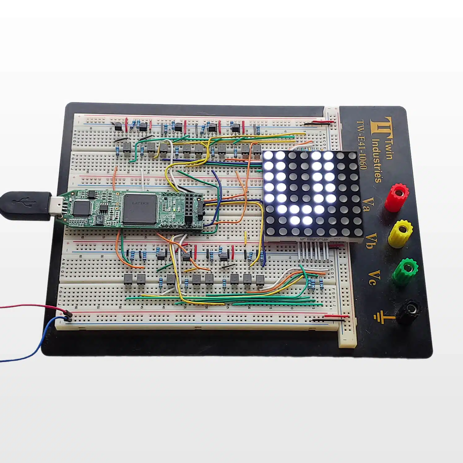
Dot Matrix VHDL and FPGA Course
Original price was: $297.$148.50Current price is: $148.50.
Learn how to create a VHDL project from scratch with self-checking testbenches. Dot Matrix is the most extensive course VHDLwhiz has ever made.
Description
Are you learning VHDL? Do you still feel like you couldn’t manage an FPGA project on your own?
Learn what they don’t teach you at the university: how to create a real-world FPGA design from scratch to a working prototype.
The Dot Matrix LED Controller FPGA Course teaches you proven VHDL methodologies that will increase your confidence as an FPGA engineer.
Trial and error is not a viable strategy when developing hardware. Learn how to structure your project and create a suite of self-checking testbenches like a professional FPGA engineer.
Get it right the first time you power on the chip.
The lessons teach you valuable skills for understanding how each code line translates into digital logic.
This course will take you from the beginner or intermediate level to being able to understand and use advanced VHDL coding constructs.
View the video below to see what you get when you buy the course!
You can read more on the original course sales page:
Dot Matrix VHDL and FPGA Course – VHDLwhiz Academy
Obsoletion discount
Notice:
I’m offering a 50% discount on this course because some original parts have become obsolete, including the 8×8 display.
But you can do the Dot Matrix course as a pure simulation exercise without building the physical prototype. We only use the hardware in the last of the 17 sections of the course.
The first 16 sections are simulation and synthesis exercises in the simulator and the Lattice implementation software (ModelSim, iCEcube2, and Synplify Pro).
You can find equivalent parts if you still want to build the prototype. It will work with a 5×7 LED display as well. I have updated the Read-only memory / Character map package lesson with an additional VHDL package that renders all characters on the smaller display.
Send an email to jonas@vhdlwhiz.com if you have any questions.
This course is NOT available in the VHDLwhiz Membership.
You can only buy this course separately as a one-time purchase.
Hardware used in the course
- Lattice iCEstick (SKU: ICE40HX1K-STICK-EVN)
Resellers: Lattice, Farnell, Newark, Mouser, DigiKey - Bill of Materials (BOM) for building the prototype
(Note that some parts are obsolete, hence the half-price offer)
Software used in the course
I am using Windows 10 in the course. All the other software is available for free for Windows and Linux:
⚠ Notice: free educational license required
Lattice Semiconductor now charges over $350/year for the iCEcube2 software.
Fortunately, VHDLwhiz, in cooperation with Lattice, offers a 1-year educational license for iCEcube2 to customers who purchase a course that uses the iCE40 FPGA.
Reply to the purchase confirmation email to request a free license.
- Questa – Intel FPGA Edition(includes Starter Edition)
(Any version of ModelSim or QuestaSim will work) - Lattice iCEcube2 Design Software
- Microsoft Visual Studio Code
(Any editor will do) - Tera Term
(Any serial (UART) terminal program will do) - Fritzing
- Git
Course outline
The overview below shows the sections and lessons in this course.
1 – Overview
Welcome to the course! Let me give you the tour and show you how to get the most out of it.

1.1 - Welcome
Choosing this course is a step on your path to becoming a better FPGA engineer. Welcome on board!

1.2 - How to use this course
Get useful tips for how you can get the most out of this course. You can do this it in a few ways.

1.3 - About the lectures
Let's go through the course overview so that you know what to expect when you reach the sections.
2 – Getting started
Order the parts for building the prototype and get your development environment up and running.

2.1 - Purchasing the parts
These are the parts that you need to purchase to build the prototype. Here's where you can buy them.

2.2 - Using the Git repository
The Git repository allows you to checkout the code for every lecture in the entire course.

2.3 - Installing ModelSim and creating a project
I am using the student edition*+ of the ModelSim VHDL simulator in this course.

2.4 - Installing Lattice iCEcube2
Lattice iCEcube2 is the design software that translates your VHDL code into programmable logic.

2.5 - Installing VSCode with VHDL plugin
I am using the student edition of the ModelSim VHDL simulator in this course. There are many free, legal versions of ModelSim. It doesn't matter which you choose because they all look the same.

2.6 - Installing Tera Term
We will use the Tera Term terminal emulator program to communicate with the FPGA later in the course.

2.7 - Installing Fritzing
Fritzing is the open-source CAD software that I used to create the schematic and layout for the breadboard. If you want to examine the drawings more closely, you need to install this free software.
3 – Design overview
Let’s get familiar with the hardware and the design that you are going to create in this course.

3.1 - How dot matrix LED displays work
We go through the schematic of the inner circuit of the dot matrix display that we are using.

3.2 - Lattice iCEstick
Let's get familiar with the FPGA development board that we are using this course.

3.3 - VHDL modules and dataflow
We go through an overview of the VHDL modules so that you get an understanding of what you are going to create.

3.4 - LED resistor calculation
In this optional lecture, I show you how I calculated the Ohm value for the LED resistors.

3.5 - LED driver
I explain how the LED driver circuit that's activated by the 3.3V signal from the FPGA pins works.

3.6 - The complete schematic
We examine the complete analog circuit that goes onto the breadboard.
4 – Character buffer
Code your first VHDL module and run it in the simulator. Create your first self-checking testbench!

4.1 - Entity and outline of the module
We start by creating a new VHDL file that will become the char_buf module later in this section.

4.2 - Instantiating the DUT in a testbench
We create a new testbench for the char_buf module that we will use later to check its behavior.

4.3 - Creating the sampler process
The new process implements the behavior of the char_buf module by sampling the input signal on every rising edge of the clock.

4.4 - Clock and reset in the testbench
The concurrent process at the top generates the clock, while the sequencer process releases the reset.

4.5 - Constants in package
Instead of repeating the same value in several files, we assign it to a constant in a new package.

4.6 - ModelSim DO files
See how you can use DO files in ModelSim to automate tasks and create scripts for all your needs.

4.7 - Self-checking testbench using assert
Create your first self-checking testbench by using the assert statement to verify expected values.

4.8 - Exhaustive testing
The best way to verify the behavior of a module is to test all possible input value combinations.

4.9 - Checking the synthesis
Checking the synthesized netlist gives you a better understanding of the logic your code represents.
5 – Read-only memory
We create a ROM module and start to structure our project with packages and subprograms.

5.1 - How block RAM works in FPGAs
Let's talk about block RAM so that you have an understanding of how these primitives work.

5.2 - Character map package
The auto-generated package contains the rendering information for the 127 lower ASCII characters.

5.3 - Types package
It is good practice to store types and subtypes used throughout the design in a common package.

5.4 - ROM module
We create a ROM by assigning the content of the charmap package as an initial value to the signal.

5.5 - Setting up the testbench
We begin creating the testbench for the char_rom module by defining the start and end behavior.

5.6 - Subprograms package
Just like with constants and types, it's good practice to keep common subprograms in a package.

5.7 - Looping over the input values
To test all input values that we expect the char_rom module to handle, we loop over the char_range.

5.8 - Procedure for visualizing the matrix type
By printing an ASCII art representation of the DUT output, we can more easily debug failing tests by visually inspecting the output.

5.9 - Checking the synthesis
We inspect the synthesized netlist to make sure that the VHDL code gets implemented in block RAM.
6 – Tcl scripting
I talk about the Tcl scripting language and the scripts we use to run our testbenches in ModelSim.

6.1 - Why you should learn Tcl
You can use Tcl for creating scripts and in the console of many different FPGA tools and simulators.

6.2 - Loading and running the testbench
The supplied Tcl script is for your convenience. Use it for running your testbenches with ease.

6.3 - Regression testing
Use the regression test script to check the integrity of the whole project after making changes.
7 – Testbench FIFO
Learn how to use the object-oriented features of VHDL to create a testbench for the FIFO module.

7.1 - FIFOs and linked lists
Let's agree on what a FIFO is and what a linked list is before we start coding.

7.2 - Declaring the protected type
Protected types in VHDL are similar to classes in other object-oriented programming languages.

7.3 - Record and access type
Records are storage containers for multiple elements. Access types are pointers to dynamic objects.

7.4 - The push procedure
We create a procedure that assigns an element to a new dynamic object and appends it to the list.

7.5 - The pop function
To pop an element, we disconnect the oldest object from the list and unpack it from the container.

7.6 - The peek and empty functions
These utility functions are for checking what the oldest element in the list is and if it's empty.

7.7 - Testbench for the testbench fifo
We must create a testbench for the sim_fifo, even though it's intended for use within a simulator.

7.8 - Testing push peek and pop
To test that the sim_fifo works, we will fill the linked list with known values and empty it again.
8 – UART receiver
We use a finite-state machine to receive the characters that arrive from the computer over USB.

8.1 - Defining the entity
We create the entity and outline for a new VHDL file that will become the UART receiver module.

8.2 - The finite-state machine
The best way to implement an algorithm in an FPGA is to translate it into a finite-state machine.

8.3 - Counting clock cycles
To delay the transitions between FSM states, we need to measure real-time by counting clock cycles.

8.4 - Preliminary testbench
We start creating the common testbench for the UART modules that we will finish in a later section.

8.5 - Counting data bits
We need to stay in the SAMPLE_DATA state for the duration of eight data bits to sample one byte.

8.6 - Shift register
To capture each transmitted byte, we are going to use a shift-register with room for eight bits.

8.7 - The stop bit error output
An easy check is to look at the received stop bit. A low value indicates an error in the transfer.

8.8 - Checking the synthesis
Inspection of the synthesis logs reveals that our named FSM states translate to binary values.
9 – UART transmitter
To verify that the FPGA decodes the characters correctly, we transmit them back to the computer.

9.1 - Defining the entity
We start creating the UART transmitter by defining the entity with the input and output signals.

9.2 - The finite-state machine
To keep track of where we are in the transmission sequence, we will use a finite-state machine.

9.3 - Sending the start bit
The first step in sending a byte over UART is to pull the TX line low for the duration of one bit.

9.4 - Counter impure function
To avoid repeating the clock counter code, let's create a subprogram within the FSM process.

9.5 - Sending the data bits
We'll use the counter as a selector signal for a multiplexer containing the eight data bits to send.

9.6 - Sending the stop bit
The stop bit must always be a high value. Otherwise, it's interpreted as an error by the receiver.

9.7 - Adding the transmitter to the testbench
Instantiate the transmitter in the common UART testbench. We will complete it in the next section.

9.8 - Checking the synthesis
Let's have a look at the synthesis log for the transmitter to see if it differs from the receiver.
10 – UART self-checking testbench
By using the testbench FIFO, we can combine the UART receiver and transmitter into one testbench.

10.1 - Testbench strategy
Let's agree on what to create before we start coding the common testbench for the UART modules.

10.2 - Transmit procedure
To keep our sequencer process neat, we are going to create a procedure for transmitting a byte.

10.3 - Waiting until the transmitter is ready
Before sending, we have to wait until the uart_tx module reports that it's ready to accept input.

10.4 - Testing all possible input values
Because there are only 256 different values that a byte can have, we can test all possible inputs.

10.5 - RX checker process
To decouple the sender from the receiver side, we implement the checking in a separate process.

10.6 - Procedure for waiting until the FIFO is empty
Before we can stop the testbench, we need to make sure that all characters have passed through the transmitter and the receiver.

10.7 - Checking the stop bit error output
To check that the stop bit error output from the receiver is working, we provoke a stop bit error in the testbench.
11 – Reset
Let’s talk about why reset in FPGAs. We will create a testbench to simulate a button press.

11.1 - Why reset is an important subject
Let's talk about why you should think about the behavior of the reset logic when coding in VHDL.

11.2 - Creating the reset module
The iCE40 FPGA has an optional internal pull-up resistor that we will use on the global reset pin.

11.3 - Testbench for the reset module
We start creating the testbench for the reset module by checking that reset is active at power-on.

11.4 - Delaying by a delta cycle

11.5 - Verifying the duration of the reset strobe

11.6 - Simulate a reset button press
A reset button press shall trigger a reset strobe. We create a procedure to test this behavior.

11.7 - Checking the synthesis
Let's have a look at the synthesized netlist to see if we can recognize our VHDL code in it.
12 – LED controller
Design the module that controls which rows and columns to illuminate on the dot matrix display.

12.1 - Defining the entity
We define the entity for the module that will interface the dot matrix display rows and columns.

12.2 - Defining the LED pulse time
The LED pulse time is the duration that a row of LEDs illuminates before we more to the next row.

12.3 - The row counter
To cycle through the eight rows on the dot matrix display, we will use a 3-bit unsigned counter.

12.4 - The row and column outputs
To render the image on the display, we will assign to the rows and cols outputs in a new process.

12.5 - Deadband period
To avoid partially illuminated LEDs, we need to add a short deadband period between changing rows.

12.6 - Assert statements for synthesis
We can use assert statements also during synthesis to verify that constant values are as expected.

12.7 - Checking the synthesis
Let's see if we can make sense of the synthesized netlist for the LED controller module.
13 – LED controller self-checking testbench
The testbench supplies the DUT with input values and renders the output character in the console.

13.1 - Testbench strategy
Let's talk about how this testbench is going to work before we start coding anything at all.

13.2 - Instantiating the DUT
As always, we start creating the testbench by instantiating the DUT and mapping the port signals.

13.3 - Speeding up the simulation
To speed up the simulation, we pass shorter pulse and deadband times to the DUT in the testbench.

13.4 - Looping through all input characters
We cycle through the array that contains all the input values that we expect the DUT to handle.

13.5 - Defining a verification component
The verification component will monitor the input that we send to the DUT as well as its output.

13.6 - Instantiating the verification component
We instantiate the verification component parallel to the DUT so that it can monitor its behavior.

13.7 - Interfacing the verification component
We need to tell the verification component when we expect the output from the DUT to be stable.

13.8 - Printing the input and output character
Printing the rendered character before we stop the failing test will help us in debugging errors.
14 – LED controller verification component
To reduce the complexity of the testbench, we move parts of the code into a new verification module.

14.1 - Modelling the dot matrix display
First, we create data structures that can accurately model the behavior of the dot matrix display.

14.2 - Process for checking the pattern
We start on creating the process that will check if the DUT is rendering the character correctly.

14.3 - The touch_leds procedure
The new procedure will store the rendered pattern produced by the row by row scanning of the DUT.

14.4 - The get_event function
To circumvent a shortcoming of VHDL, we create a function to check for events on vector members.

14.5 - The to_matrix_type function
We create a conveniency function to translate from a matrix of integers to a matrix of std_logic.

14.6 - The check_leds procedure 1
We start creating a procedure that will eventually check that the DUT output matches the template.

14.7 - The check_leds procedure 2
We complete the procedure, and we test that it works by using the ModelSim force freeze command.

14.8 - Process for checking the pulse duration
We create a new process that will check that the duration of every LED pulse is within a min-max interval.

14.9 - The check_pulse_time procedure
We use our get_event function and the 'last_value attribute to determine the length of the pulse.

14.10 - The get_last_value and get_last_event functions
The 'last_value and 'last_event attributes are not allowed on vector members, but it can be done.

14.11 - Checking the pulse duration
We define acceptable minimum and maximum values for what the duration of the LED pulses can be.

14.12 - Checking the deadband duration
We also need to check that the OFF period between illuminating rows is above a minimum duration.

14.13 - Testing the testbench
You should never trust a test that hasn't failed yet. Let's create artificial errors in our code to verify that the testbench catches them.
15 – Top-level structural module
The top module contains all of the other modules and defines the interfaces between them.

15.1 - Top-level entity
We define the signals on the top-level entity, which are in direct control of IO pins on the FPGA.

15.2 - Instantiating the RTL modules
We begin to instantiate all of the RTL modules that go into our design inside of the top module.

15.3 - Top-level signals
We map signals between the RTL modules to implement the interface shown in the dataflow diagram.

15.4 - The debug_leds module 1
To get useful information from the debug LEDs, we will create a new module for controlling them.

15.5 - The debug_leds module 2
The debug_leds module will notify us of known error conditions by lighting predefined debug LEDs.

15.6 - Checking the synthesis
Let's check the synthesized netlist for the complete design, and see how much resources it uses.

15.7 - Pin assignment and constraints
To complete the design, you must assign the top-level entity signals to physical pins on the FPGA.
16 – Top-level testbench
With the help of our reusable verification component, we will create the top-level testbench easily.

16.1 - Instantiating the DUT
The first step of creating the top testbench is to instantiate the top-level structural module.

16.2 - Instantiating the UART_TX module
We are going to use the UART_TX module to emulate the host computer sending commands to the DUT.

16.3 - Instantiating the verification component
We can reuse the verification component from the LED controller testbench to check the outputs.

16.4 - The sequencer process
We use hierarchical signal access to wait for the DUT to release its internally generated reset.

16.5 - The check_output procedure
The new convenience procedure checks that the character rendered by the DUT matches the template.

16.6 - The self-checking testbench
To verify that the top module works for all supported characters, we will cycle through them all.

16.7 - Interactive testbench
In the interactive mode, you control the flow of the testbench by typing commands in the console.
17 – Constructing the prototype
Finally, it’s time for us to build the prototype. Will it work when you power on the board?

17.1 - Soldering iCEstick
You have to solder on two racks of header pins so that you can place the iCEstick on a breadboard.

17.2 - Converting a USB cable to a power supply
I show you how to convert a USB cable to a 5V power supply to power the LEDs on your breadboard.

17.3 - Assembling the breadboard
Let me give you my tips for how you can assemble the circuit on the breadboard without problems.

17.4 - Testing the circuit
You should test the circuit before you mount the iCEstick to avoid damaging the FPGA.

17.5 - Programming the FPGA
Download the software from this URL:Click here to download Diamond Programmer

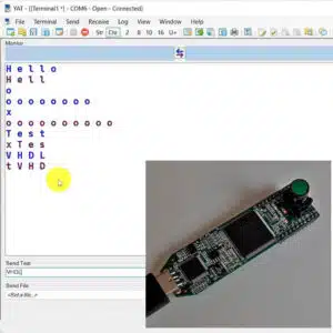
17.6 - Testing using Tera Term for sending data
Let me show you how to set up the Tera Term program to send data to the FPGA.

17.7 - Fixing the mirrored characters
To fix the problem with mirrored characters, we will remap the control pins for the LED columns.

17.8 - Fixing the UART problem
Let's find a solution to the problem of characters arriving too fast over UART from the computer.

17.9 - Congratulations!
Woohoo, you did it! You've completed the course! Go on to request your Certificate of Achievement.

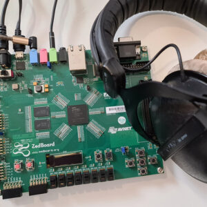
17.10 - Join the VHDLwhiz Membership
NEW VIDEO! The VHDLwhiz Membership is an FPGA learning experience that never ends. And you can join now!
This course is NOT available in the VHDLwhiz Membership.
You can only buy this course separately as a one-time purchase.
⚠ Notice: free educational license required
Lattice Semiconductor now charges over $350/year for the iCEcube2 software.
Fortunately, VHDLwhiz, in cooperation with Lattice, offers a 1-year educational license for iCEcube2 to customers who purchase a course that uses the iCE40 FPGA.
Reply to the purchase confirmation email to request a free license.
Reviews
There are no reviews yet.