Course: FPGA and VHDL Fast-Track
$27
Hands-On for Absolute Beginners. Understand the basics of FPGA development using VHDL in a few evenings!
Description
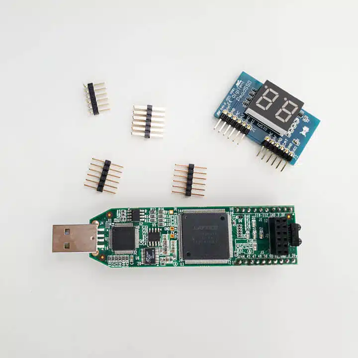
Understand the basics of FPGA development using VHDL in a few evenings! This course is for students and IT professionals who need a fast run-down of the subject. With this course and the low-cost Lattice iCEstick development board, you will be developing real hardware within hours.
When you buy the Fast-Track, you will get permanent access to it through the dedicated course platform on academy.vhdlwhiz.com.
👉 Click here to read everything about the FPGA and VHDL Fast-Track course!
Use the link above to see more details and read the FAQ.
This course is NOT available in the VHDLwhiz Membership.
You can only buy this course separately as a one-time purchase.
⚠ Notice: free educational license required
Lattice Semiconductor now charges over $350/year for the iCEcube2 software.
Fortunately, VHDLwhiz, in cooperation with Lattice, offers a 1-year educational license for iCEcube2 to customers who purchase a course that uses the iCE40 FPGA.
Reply to the purchase confirmation email to request a free license.
Course outline
The overview below shows the lessons you can access after purchasing this course.
1 – Introduction

Welcome to the Fast-Track
Get ready to start your journey into the land of programmable logic. Welcome on board!

How to use this course most efficiently
Let me shown you around the course platform so that you can get the most out of this course.
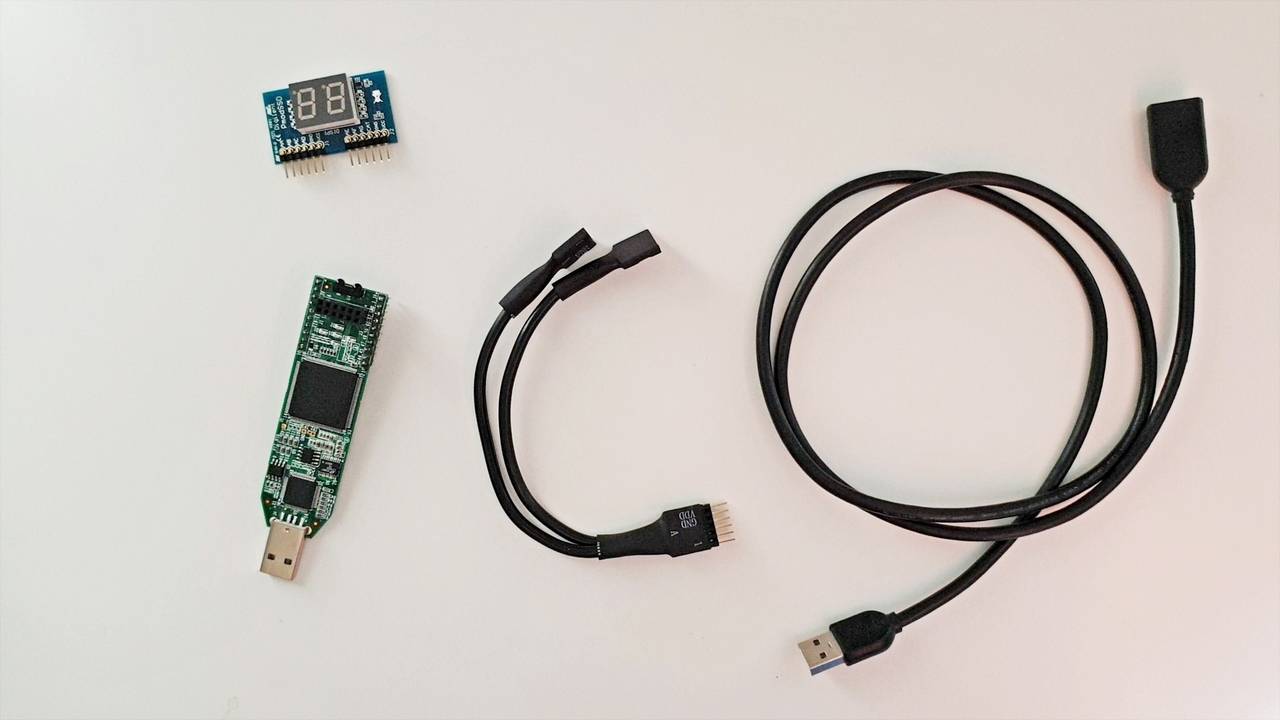
This is what you need to get started
These are the parts that you need, and this is where you can purchase them.
2 – This is how FPGA development works
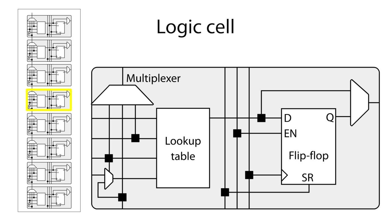
The basic building blocks of an FPGA
The FPGA consists of columns of programmable logic blocks (PLBs), block RAM (BRAM).
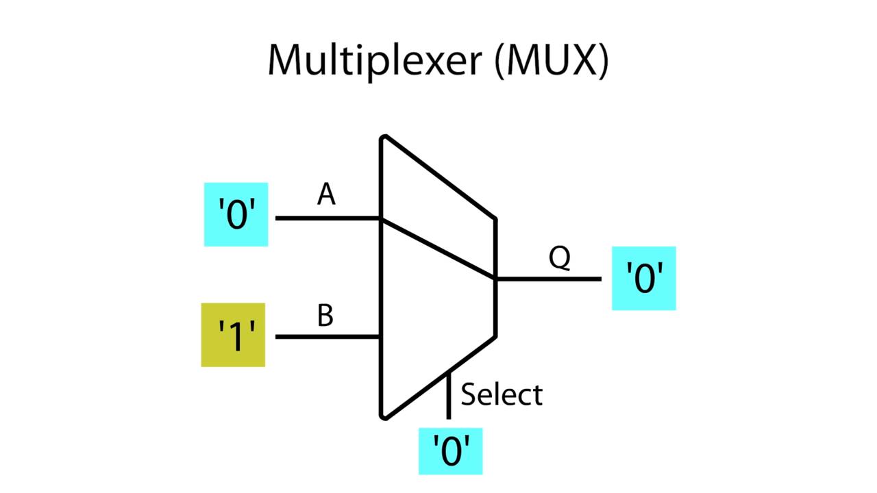
The multiplexer (MUX)
The multiplexer is one of the basic primitives found inside of an FPGA.
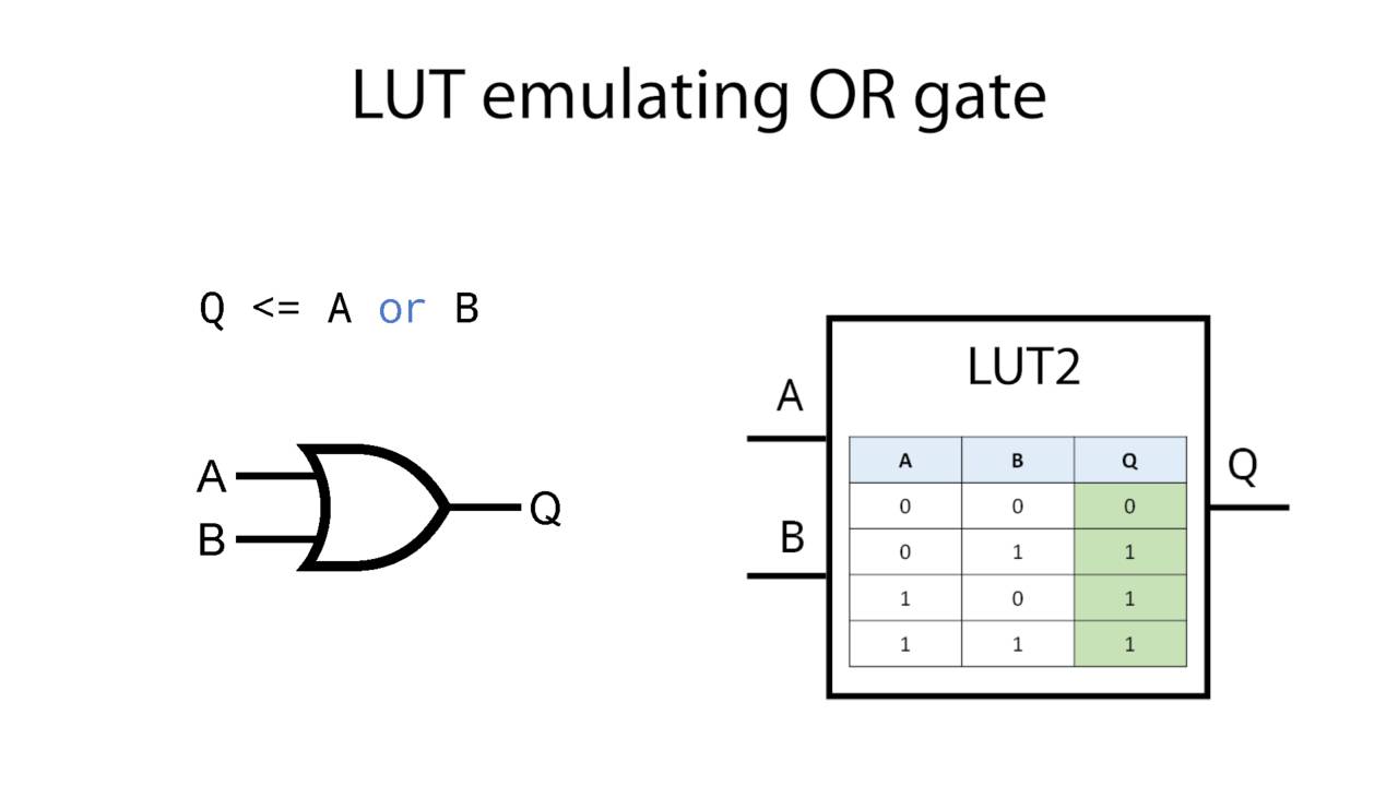
The lookup table (LUT)
The lookup tables in the iCE40 FPGA uses static RAM to emulate of Boolean logic gates.

The flip-flop (FF)
The flip-flop is an edge-triggered device. It's output only changes on the clock edges.

Synthesis, Place and Route
VHDL code gets translated into digital logic on the FPGA in two main steps: Synthesis and P & R.
3 – Setting up the software tools
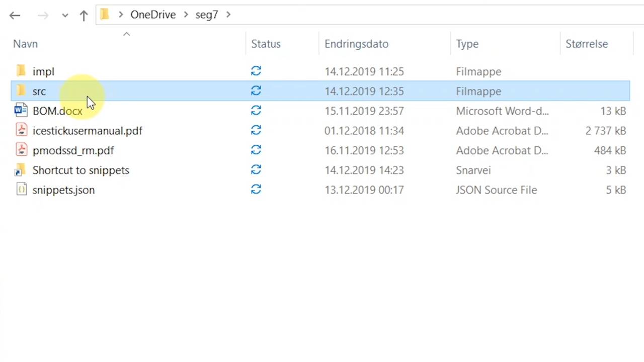
Download the resource Zip
I have prepared a Zip file with everything you need to get started with this course.

Setting up the VSCode editor
I will use the Visual Studio Code editor from Microsoft with a VHDL plugin in this course.
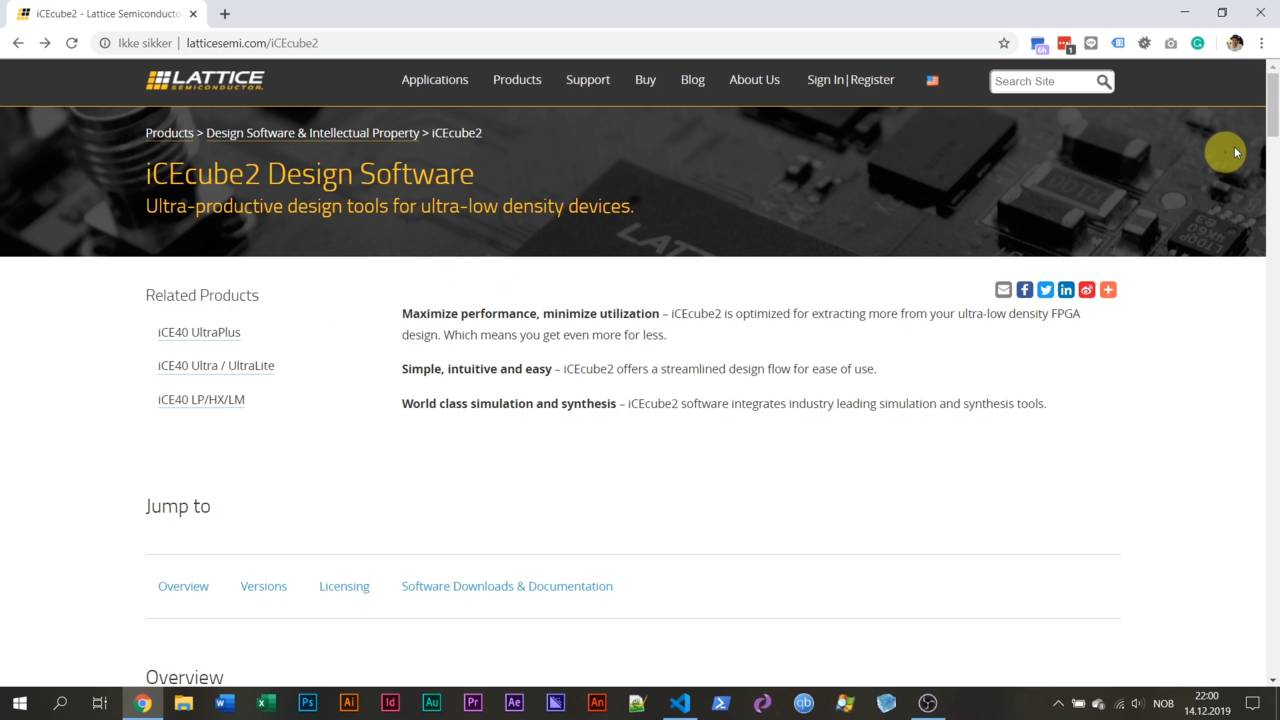
Installing Lattice iCEcube2 and ModelSim
Let's install the iCEcube2 design software, which comes with ModelSim, the most popular VHDL simulator.
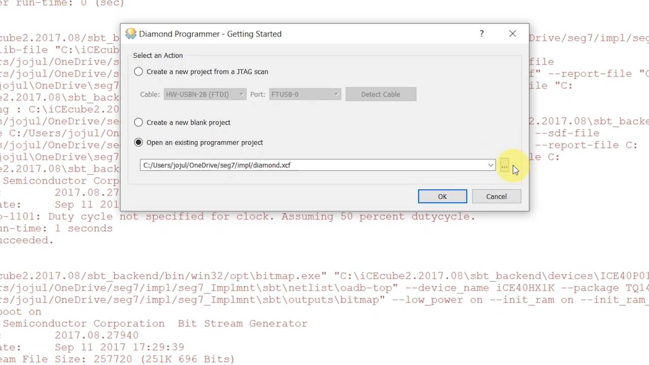
Setting up Diamond Programmer
See how to set up the Diamond Programmer to work with the Lattice iCEstick FPGA development board.
4 – Let’s start coding VHDL!
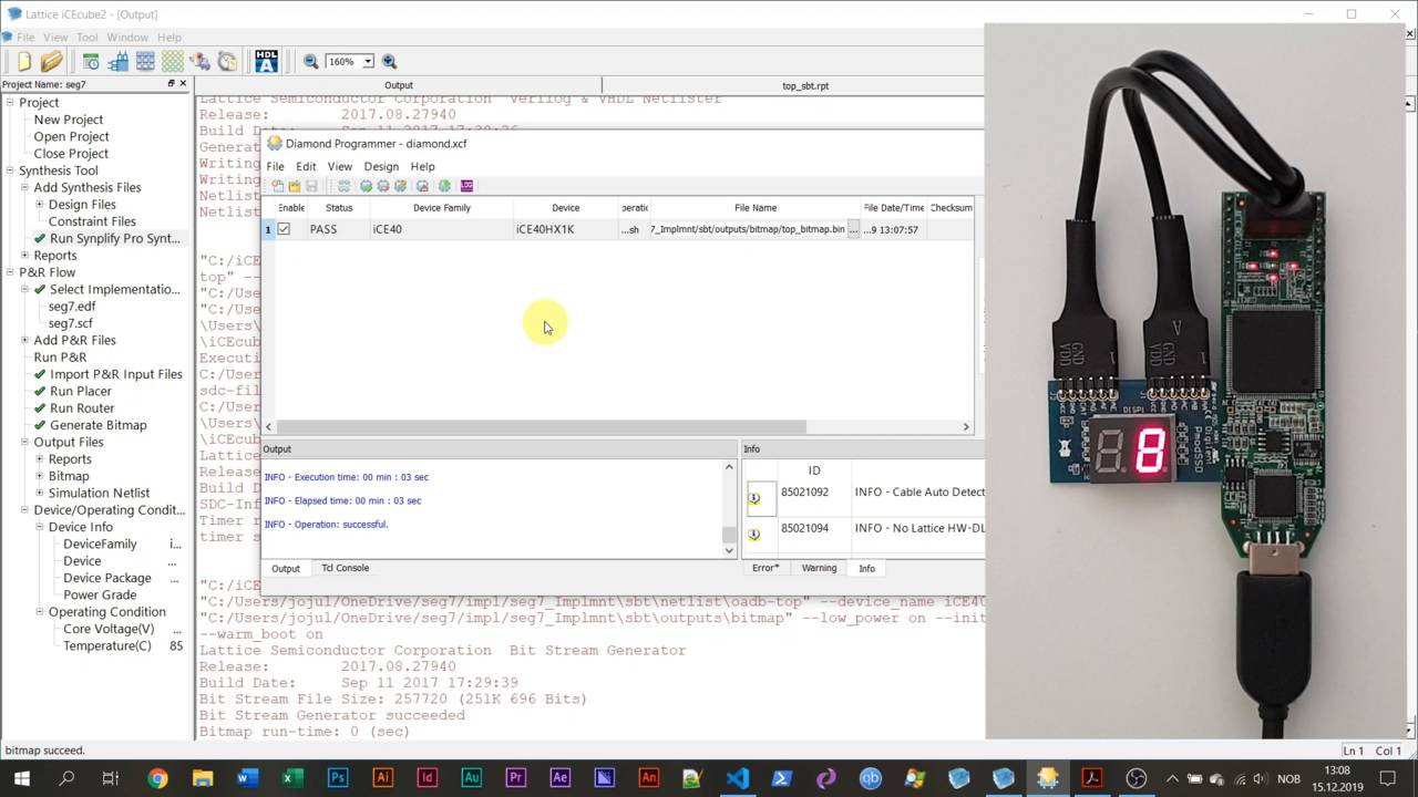
Your first VHDL program running on the FPGA
Get your first VHDL program running on the FPGA and see the results on the 7-segment display.
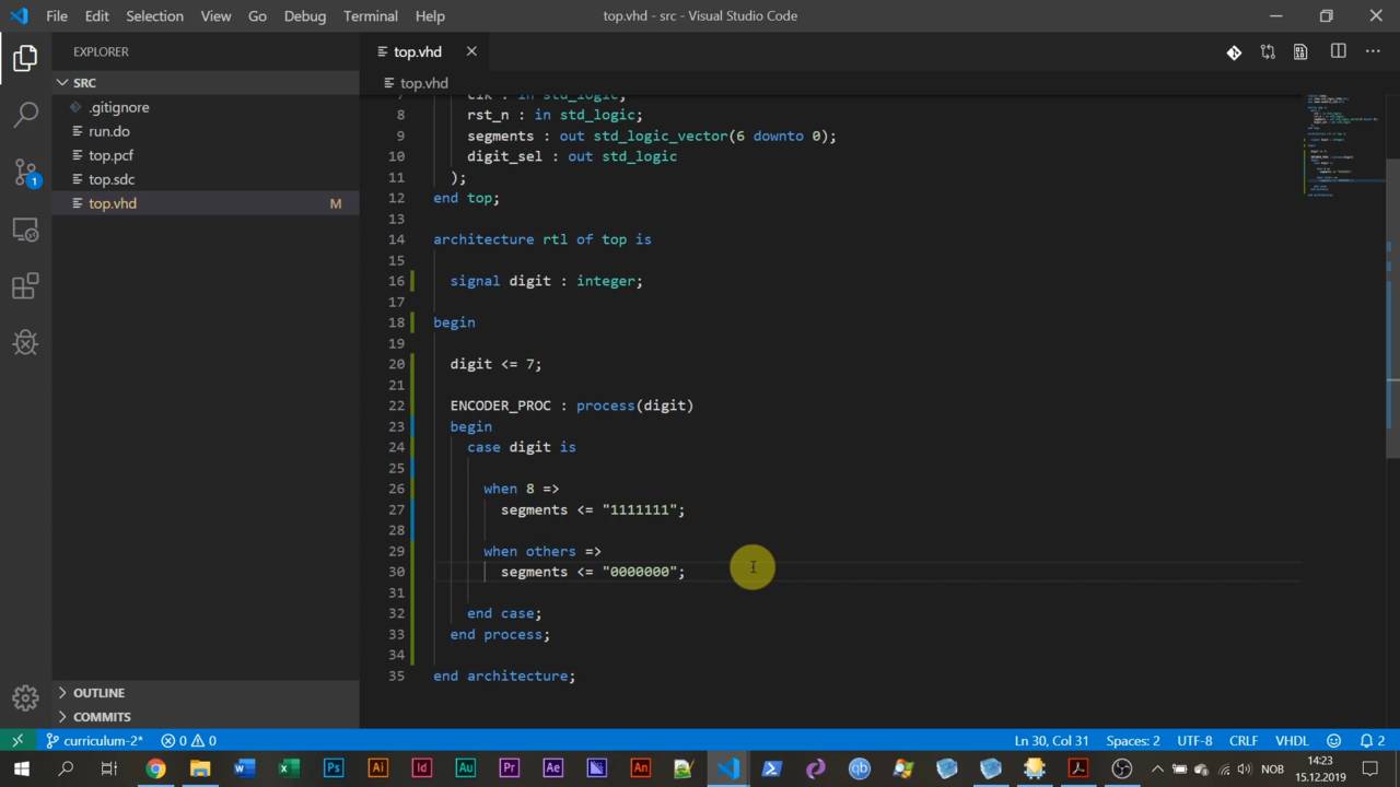
Process with a sensitivity list and case statement
Learn how to create a process with a sensitivity list. Also, see how the case-when statement works.
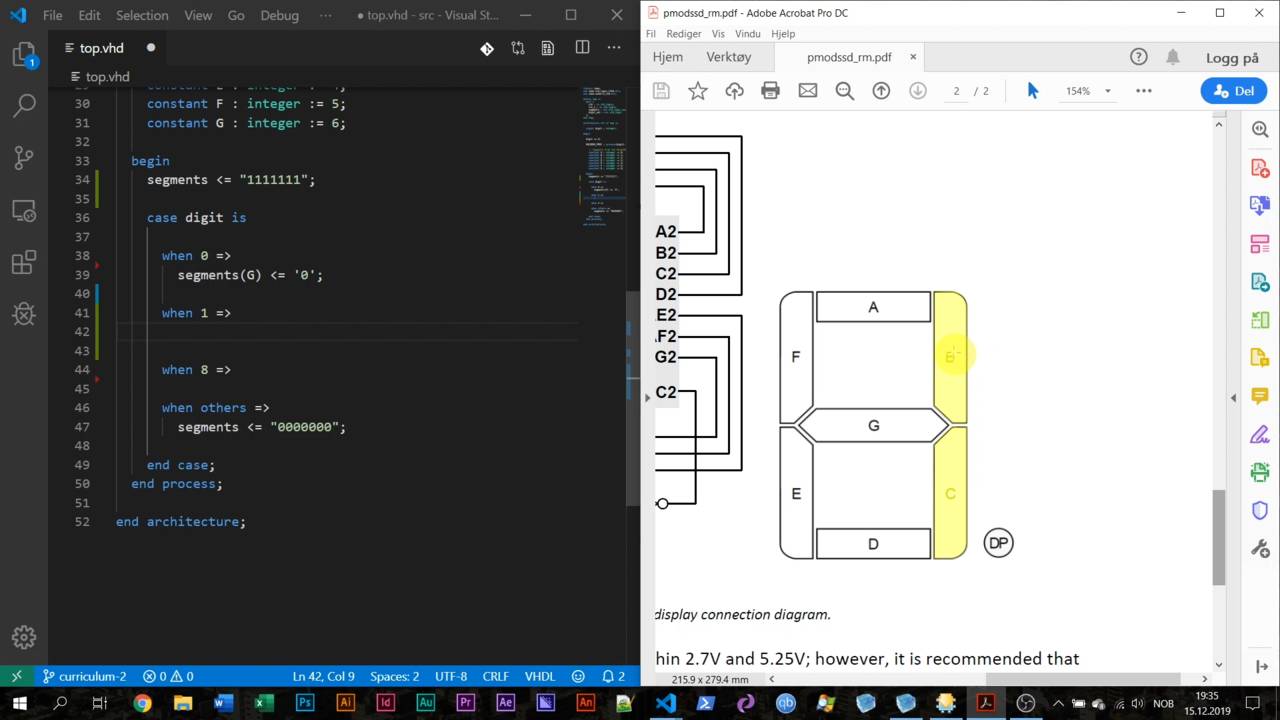
How signal scheduling works in VHDL
We declare constant values in the declarative region of a process, and we use them to index a vector.
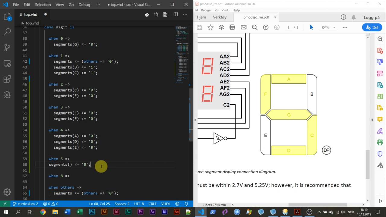
Aggregate assignment using OTHERS
The aggregate assignment is a dynamic way to give all of the bits within a vector the same value.
5 – The VHDL simulator and testbench
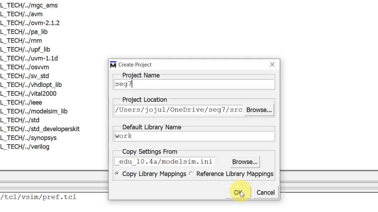
Start a new project in ModelSim
This lecture is a walk-through of how to set up a new VHDL project in the ModelSim simulator.
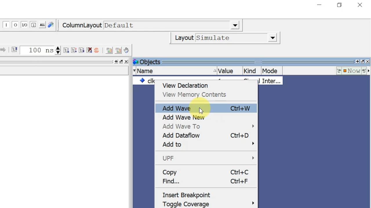
Create a testbench and simulate in ModelSim
Before we can simulate our VHDL module, we need to create a VHDL test program called a testbench.
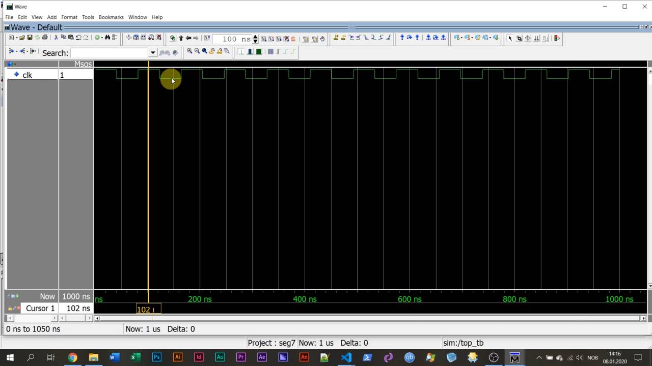
Generate the clock signal using WAIT FOR
Learn how to generate the clock signal by using a WAIT FOR statement to delay simulation time.
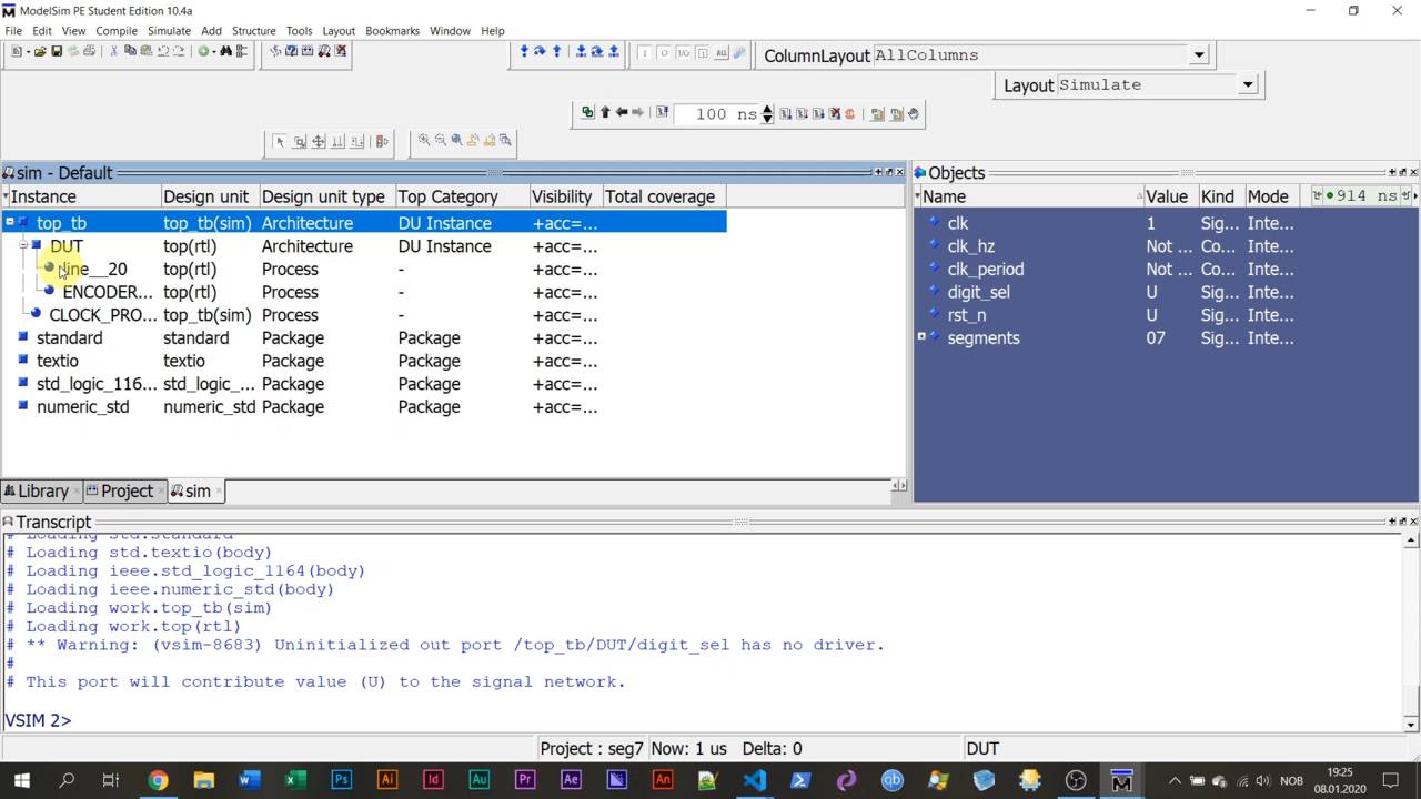
Instantiate the device under test (DUT)
We need to import our VHDL module into the testbench so that we can interact with it and observe its behavior.
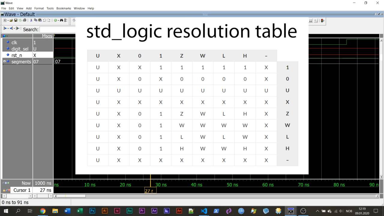
Signal metavalues: uninitialized, multiple drivers
In addition to the binary '0' and '1', the std_logic type can represent a few other metavalues.
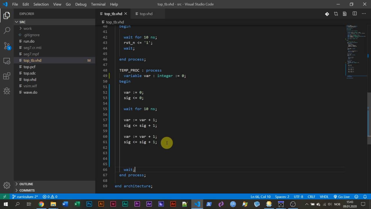
How a variable is different from a signal
VHDL has variables like any other programming language. They behave differently from signals.
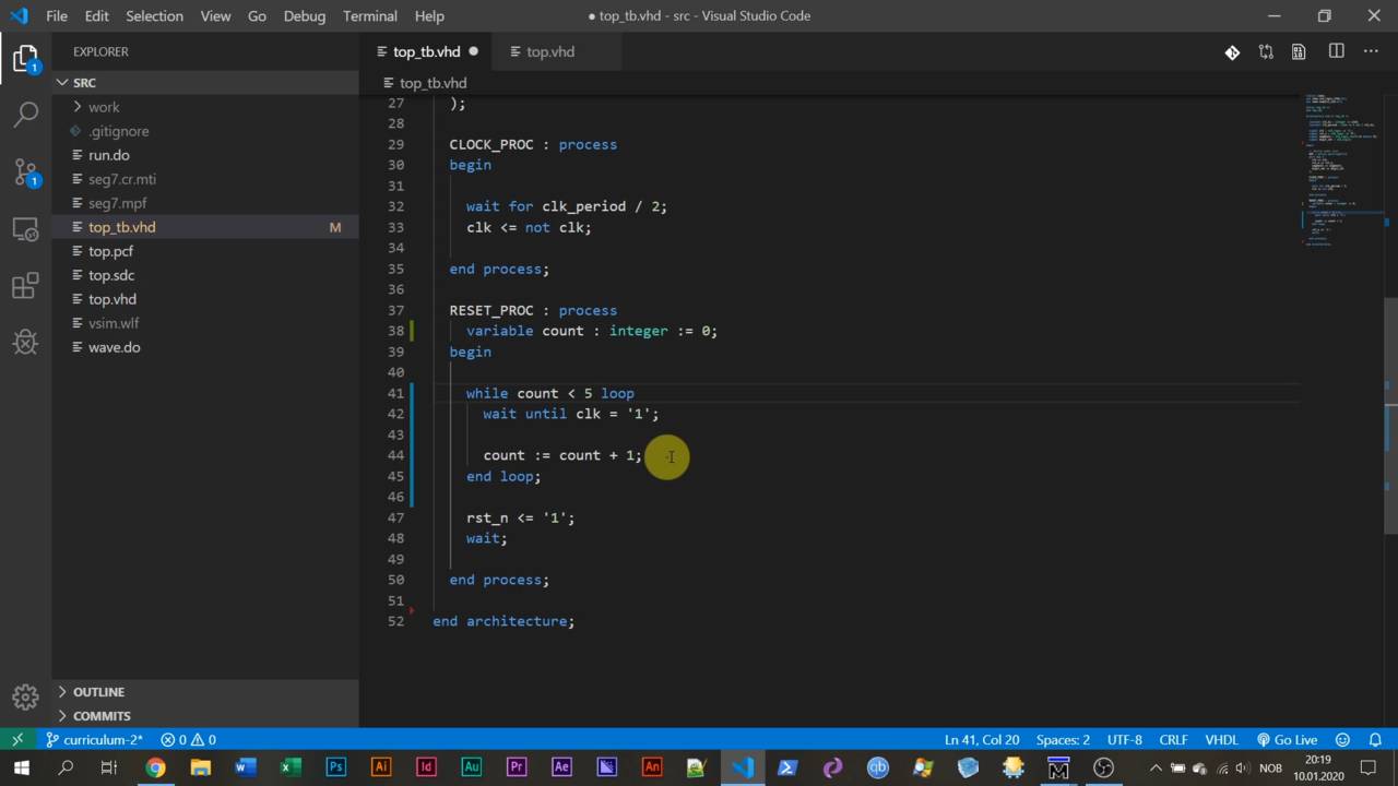
LOOP, WHILE-loop, FOR-loop, and WAIT UNTIL
Let's take a look at the different types of loops that exist in VHDL, and how we can use them.
6 – Creating clocked logic
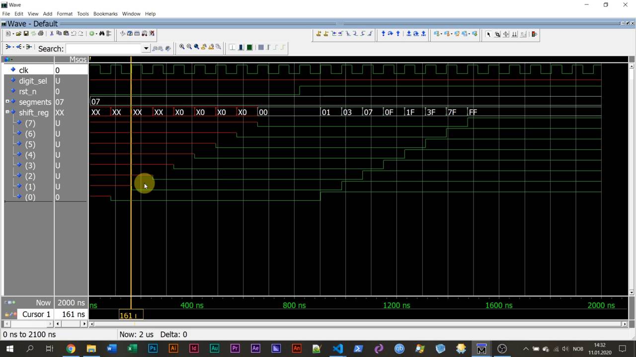
Shift-register using a synchronous process
In this lecture, we create a process that runs in sync with the clock signal.
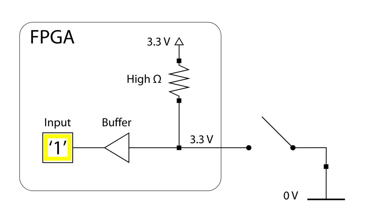
Generate the internal reset signal
Reset is an essential part of FPGA design. We have to be able to control the initial state of our logic.
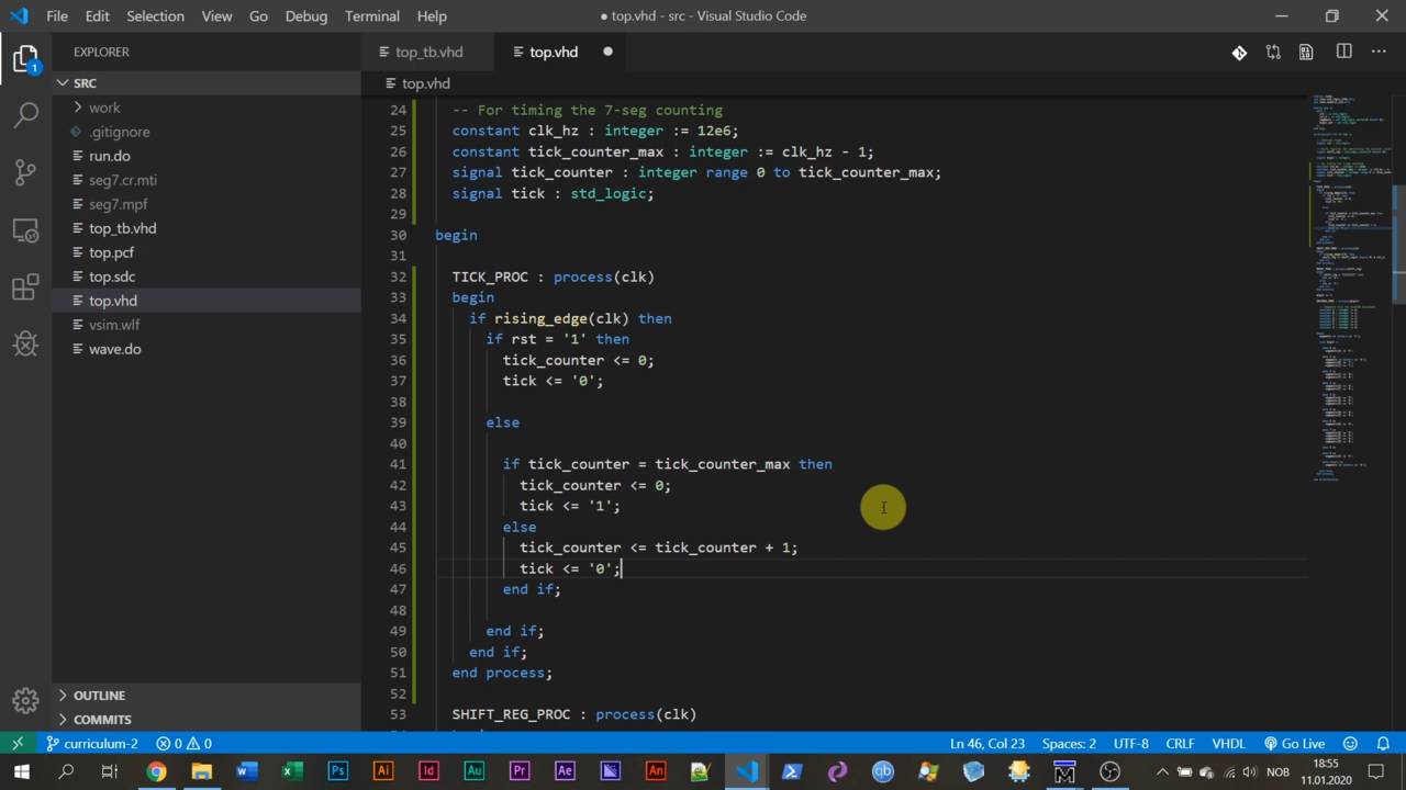
Measuring time by counting clock cycles
The signal is the only reliable source of time in the FPGA. Measuring real-time can be done by counting clock cycles.
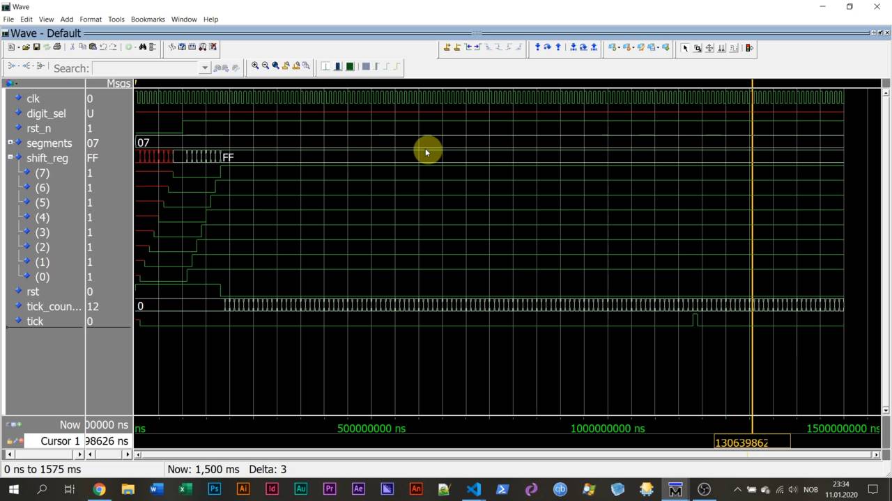
Generics used for speeding up the simulation
Generics are constant values that you can assign to a module when instantiating it.
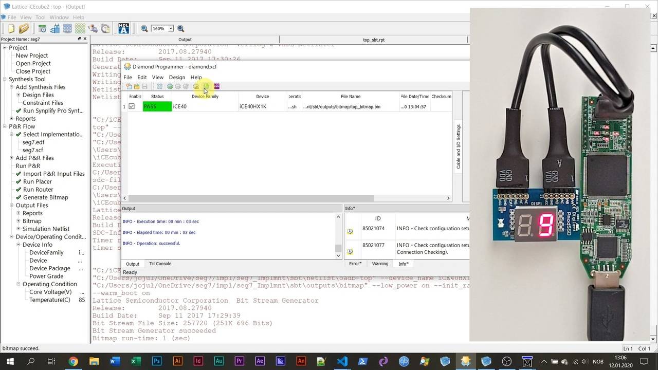
Counting seconds on the display
It's time for us to use the tick signal to count seconds from 0 to 9 on the 7-segment display.
7 – Slightly more advanced VHDL
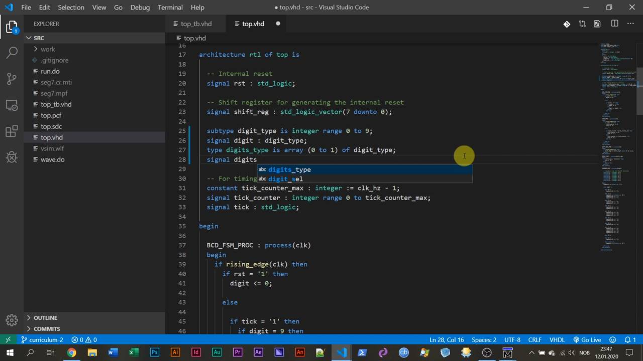
Defining a type, subtype, and array
You can define custom data types in VHVDL. It can be a subtype based on an existing type, or you can create an entirely new data type.
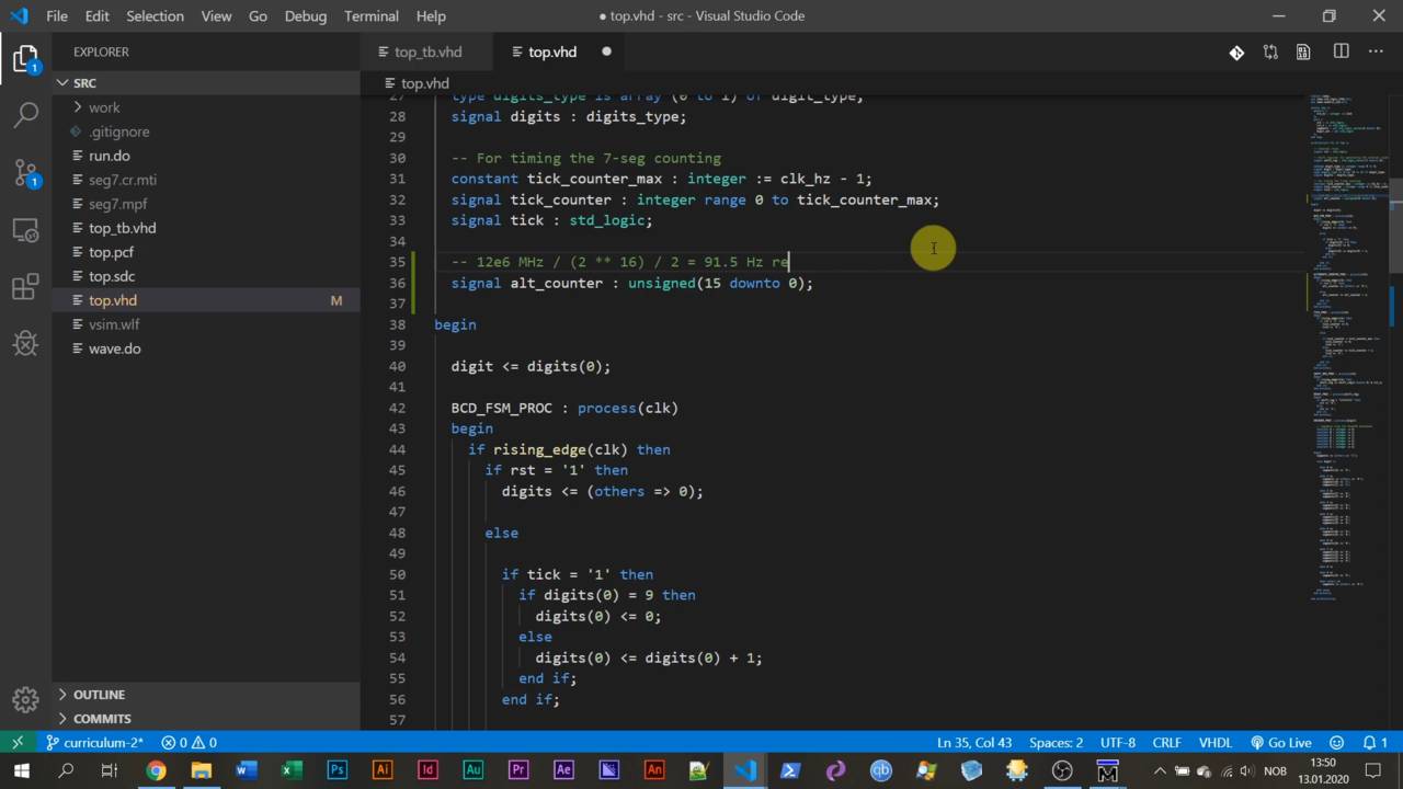
Unsigned type for self-wrapping counter
The unsigned data type behaves like a hybrid between an integer and a std_logic_vector.
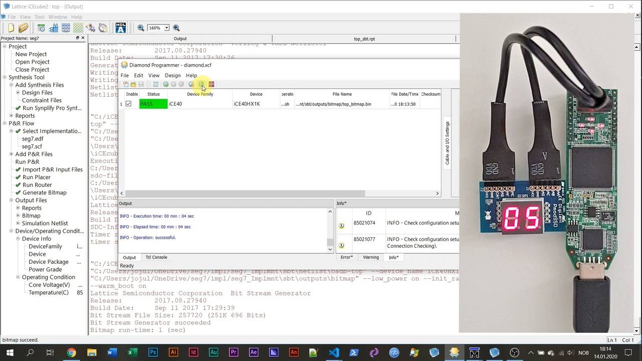
Output multiplexer and signal attributes
To alternate between the two digits on the 7-segment display, we create a multiplexer.
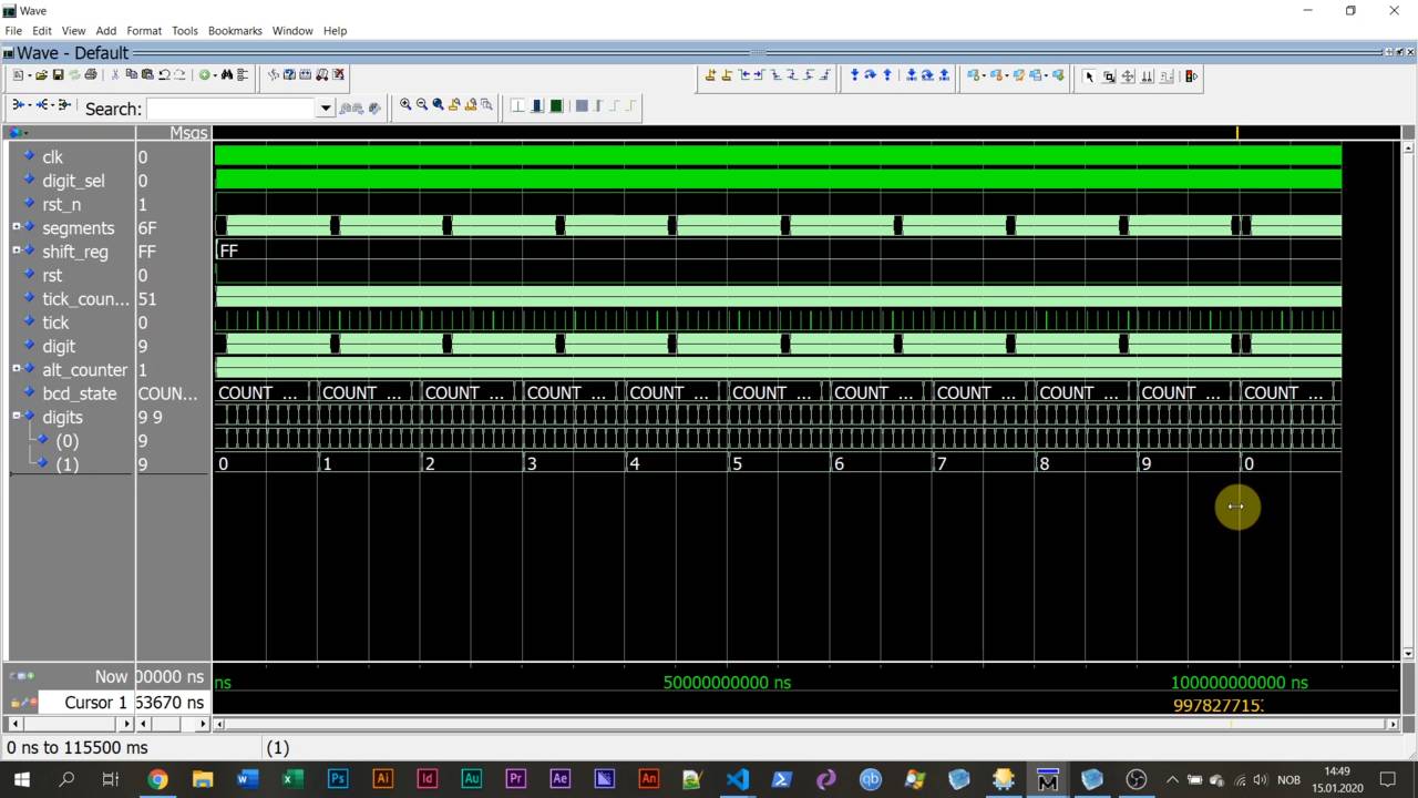
Finite-state machine for counting tens and ones
An FSM is what you need to use to implement an algorithm on an FPGA.
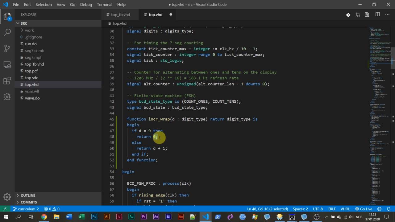
Function and procedure used for avoiding repetitive code
VHDL has two types of subprograms: the function and the procedure.

Congrats! Where to go from here
You did it! You finished the course. Congratulations! But don't stop here.


Reviews
There are no reviews yet.