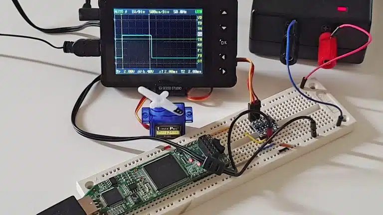
In earlier tutorials we have used the wait for statement to delay time in simulation. But what about production modules? The wait for statement cannot be used for that. That only works in simulation because we can’t just tell the electrons in a circuit to pause for a given time. So how can we keep track of time in a design module?
The answer is simply counting clock cycles. Every digital design has access to a clock signal which oscillates at a fixed, known frequency. Therefore, if we know that the clock frequency is 100 MHz, we can measure one second by counting a hundred million clock cycles.
This blog post is part of the Basic VHDL Tutorials series.
To count seconds in VHDL, we can implement a counter that counts the number of clock periods which passes. When this counter reaches the value of the clock frequency, 100 million for example, we know that a second has passed and it’s time to increment another counter. Let’s call this the Seconds counter.
To count minutes, we can implement another Minutes counter which increments when 60 seconds have passed. Similarly, we can create an Hours counter for counting hours, incrementing when 60 minutes have passed.
We can continue this approach for counting days, weeks, and months too. We are limited by the available physical resources in the underlying technology as well as the length of the counter versus the clock frequency.
As the length of the counters increases, obviously, it consumes more resources. But it will also react slower because the chain of events becomes longer.
Exercise
In this video tutorial, we will learn how to create a timer module in VHDL:
The final code for the timer testbench:
library ieee;
use ieee.std_logic_1164.all;
use ieee.numeric_std.all;

entity T18_TimerTb is
end entity;

architecture sim of T18_TimerTb is

    -- We're slowing down the clock to speed up simulation time
    constant ClockFrequencyHz : integer := 10; -- 10 Hz
    constant ClockPeriod      : time := 1000 ms / ClockFrequencyHz;

    signal Clk     : std_logic := '1';
    signal nRst    : std_logic := '0';
    signal Seconds : integer;
    signal Minutes : integer;
    signal Hours   : integer;

begin

    -- The Device Under Test (DUT)
    i_Timer : entity work.T18_Timer(rtl)
    generic map(ClockFrequencyHz => ClockFrequencyHz)
    port map (
        Clk     => Clk,
        nRst    => nRst,
        Seconds => Seconds,
        Minutes => Minutes,
        Hours   => Hours);

    -- Process for generating the clock
    Clk <= not Clk after ClockPeriod / 2;

    -- Testbench sequence
    process is
    begin
        wait until rising_edge(Clk);
        wait until rising_edge(Clk);

        -- Take the DUT out of reset
        nRst <= '1';

        wait;
    end process;

end architecture;
The final code for the timer module:
library ieee;
use ieee.std_logic_1164.all;
use ieee.numeric_std.all;

entity T18_Timer is
generic(ClockFrequencyHz : integer);
port(
    Clk     : in std_logic;
    nRst    : in std_logic; -- Negative reset
    Seconds : inout integer;
    Minutes : inout integer;
    Hours   : inout integer);
end entity;

architecture rtl of T18_Timer is

    -- Signal for counting clock periods
    signal Ticks : integer;

begin

    process(Clk) is
    begin
        if rising_edge(Clk) then

            -- If the negative reset signal is active
            if nRst = '0' then
                Ticks   <= 0;
                Seconds <= 0;
                Minutes <= 0;
                Hours   <= 0;
            else

                -- True once every second
                if Ticks = ClockFrequencyHz - 1 then
                    Ticks <= 0;

                    -- True once every minute
                    if Seconds = 59 then
                        Seconds <= 0;

                        -- True once every hour
                        if Minutes = 59 then
                            Minutes <= 0;

                            -- True once a day
                            if Hours = 23 then
                                Hours <= 0;
                            else
                                Hours <= Hours + 1;
                            end if;

                        else
                            Minutes <= Minutes + 1;
                        end if;

                    else
                        Seconds <= Seconds + 1;
                    end if;

                else
                    Ticks <= Ticks + 1;
                end if;

            end if;
        end if;
    end process;

end architecture;
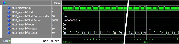
The waveform zoomed in on the Seconds signal:
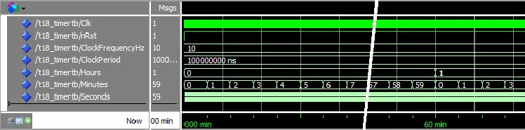
The waveform zoomed in on the Minutes signal:
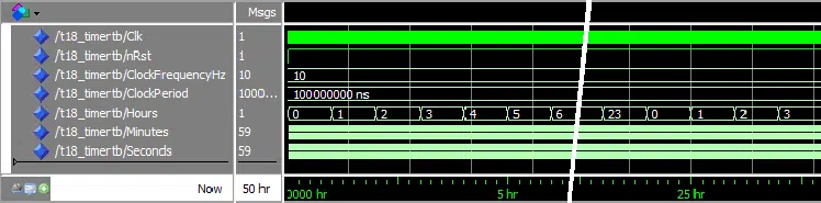
The waveform zoomed in on the Hours signal:
Need the Questa/ModelSim project files?
Let me send you a Zip with everything you need to get started in 30 seconds
Tested on Windows and Linux Loading Gif.. 
Analysis
To run a 50 hour simulation we gave the command run 50 hr in the ModelSim console. Fifty hours is a really long simulation, and therefore we had to lower the clock frequency in the testbench to 10 Hz. If we had left it at 100 MHz, the simulation would have taken days. Such adaptations are sometimes necessary to allow us to simulate a design.
We right-clicked the timeline in the waveform and selected “Grid, Timeline & Cursor Control”. When changing the time unit from ns to seconds, minute, and hours, we could see that the timer was indeed working in real-time.
The timer time is slightly offset from simulation time because of the reset of the module at the beginning of the simulation. It’s visible in the first waveform where the 60-second mark on the timeline is slightly before when the Seconds signal wraps to 0.
Note that in simulation, the counter values are updated in zero time at the rising edge of the clock. In the real world, the counter value will need some time to propagate from the first bit of the counter to the last one. As we increase the length of the counters, we consume of the available time of a clock period.

If the accumulated length of all the cascaded counters become too long, an error will be produced in the place and route step after compilation. How long a counter you can implement before consuming the entire clock period depends on the FPGA or ASIC architecture and clock speed.
An increased clock speed means that the counter chain will be longer. It also means that the clock period time will be shorter, giving the counter chain even less time to complete.
Get free access to the Basic VHDL Course
Download the course material and get started.
You will receive a Zip with exercises for the 23 video lessons as VHDL files where you fill in the blanks, code answers, and a link to the course.
By submitting, you consent to receive marketing emails from VHDLwhiz (unsubscribe anytime).
Takeaway
- Measuring time in VHDL modules is achieved by counting clock cycles
- Lowering the clock frequency in the testbench will speed up the simulation


Correct the error in the code: 100e6; — 100 MHz
hi i tried to compiled by using quartus but i had a problem in this code
library ieee;
use ieee.std_logic_1164.all;
use ieee.numeric_std.all;

entity T18_TimerTb is
end entity;

architecture sim of T18_TimerTb is

    -- We're slowing down the clock to speed up simulation time
    constant ClockFrequencyHz : integer := 10; -- 10 Hz
    constant ClockPeriod      : time := 1000 ms / ClockFrequencyHz;

    signal Clk     : std_logic := '1';
    signal nRst    : std_logic := '0';
    signal Seconds : integer;
    signal Minutes : integer;
    signal Hours   : integer;

begin

    -- The Device Under Test (DUT)
    i_Timer : entity work.T18_Timer(rtl)
    generic map(ClockFrequencyHz => ClockFrequencyHz)
    port map (
        Clk     => Clk,
        nRst    => nRst,
        Seconds => Seconds,
        Minutes => Minutes,
        Hours   => Hours);

    -- Process for generating the clock
    Clk <= not Clk after ClockPeriod / 2;

    -- Testbench sequence
    process is
    begin
        wait until rising_edge(Clk);

        wait until rising_edge(Clk);

        -- Take the DUT out of reset
        nRst <= '1';
        wait;

	end process;

end architecture;
it says
Error (10398): VHDL Process Statement error at T18_TimerTb.vhd(40): Process Statement must contain only one Wait Statement
You are probably trying to synthesize the testbench. It’s only the Timer module that’s synthesizable, not the testbench. The testbench can only be run in a VHDL simulator.
To run the simulation, you will have to open the design in the VHDL simulator that you are using with Quartus, for example ModelSim. I don’t have Quartus at hand, so I don’t know the exact steps required.
hi good day, how can I output the real time clock on 7-segment displays on the FPGA ?
You have to create a process that translates from the decimal digits into illuminating segments on the display. See the example code below where I have done it for the digit “0”.
process(digit)
begin

  case digit is

    when 0 =>
      segmentA <= '1';
      segmentB <= '1';
      segmentC <= '1';
      segmentD <= '1';
      segmentE <= '1';
      segmentF <= '1';
      segmentG <= '0';

    -- Create a when-statement for each digit 0-9

  end case;
end process;
I’m launching beginner’s VHDL and FPGA course on Udemy early next year. We create a 7-segment display counter in the tutorial. Perhaps this is something you should check out.
Click here to read more about the course:
FPGA and VHDL Fast-Track:
Hands-On for Absolute Beginners
# Reading C:/intelFPGA_pro/19.3/modelsim_ase/tcl/vsim/pref.tcl
# Loading project T18_TimerTb
# Compile of T18_TimerTb.vhd was successful.
vsim work.t18_timer
# vsim work.t18_timer
# Start time: 01:03:38 on Jan 05,2020
# Loading std.standard
# Loading std.textio(body)
# Loading ieee.std_logic_1164(body)
# Loading ieee.numeric_std(body)
# Loading work.t18_timer(rtl)
# ** Fatal: (vsim-3350) Generic “ClockFrequencyHz” has not been given a value.
# Time: 0 ps Iteration: 0 Instance: /t18_timer File: C:/intelFPGA_pro/19.3/T18_TimerTb.vhd Line: 6
# FATAL ERROR while loading design
# Error loading design
# End time: 01:03:38 on Jan 05,2020, Elapsed time: 0:00:00
# Errors: 1, Warnings: 0
vsim work.t18_timertb
# vsim work.t18_timertb
# Start time: 01:03:43 on Jan 05,2020
# Loading std.standard
# ** Error: (vsim-3173) Entity ‘C:/intelFPGA_pro/19.3/work.t18_timertb’ has no architecture.
# Error loading design
# End time: 01:03:43 on Jan 05,2020, Elapsed time: 0:00:00
# Errors: 1, Warnings: 0
vcom -work work -2002 -explicit C:/intelFPGA_pro/19.3/T18_TimerTb.vhd
# Model Technology ModelSim – Intel FPGA Edition vcom 2019.2 Compiler 2019.04 Apr 17 2019
# Start time: 01:03:51 on Jan 05,2020
# vcom -reportprogress 300 -work work -2002 -explicit C:/intelFPGA_pro/19.3/T18_TimerTb.vhd
# — Loading package STANDARD
# — Loading package TEXTIO
# — Loading package std_logic_1164
# — Loading package NUMERIC_STD
# — Compiling entity T18_Timer
# — Compiling architecture rtl of T18_Timer
# End time: 01:03:51 on Jan 05,2020, Elapsed time: 0:00:00
# Errors: 0, Warnings: 0
vsim work.t18_timertb
# vsim work.t18_timertb
# Start time: 01:03:56 on Jan 05,2020
# Loading std.standard
# ** Error: (vsim-3173) Entity ‘C:/intelFPGA_pro/19.3/work.t18_timertb’ has no architecture.
# Error loading design
# End time: 01:03:56 on Jan 05,2020, Elapsed time: 0:00:00
# Errors: 1, Warnings: 0
this message pop up to me after i try to simulate your code in modelsim sir, can you please clarify what is the exact wrong , because i couldn’t get what is the error.
by the wa the compilation done perfectly.
thanks in advance.
Hi Eihab,
You are getting this error because you are running the Timer module as the top-level object while you should have been running the testbench.
Select the t18_timertb entity in the Start Simulation dialog in ModelSim instead of t18_timer. Or you can start the simulation from the ModelSim command prompt like this:
The last part of the transcript mentions that the entity “has no architecture.” I’m not sure what happened here. Check that the content of the two files is exactly the code listed in this blog post.
Hi can i use timer model file only and how can do simulate for it and if I want do timer stop at time limit how can do it ?
Hello Asmaa,
If you want to stop at a given time, you just have to stop counting when you reach those values. For example, if I wanted to stop counting at the time 09:09:09, I could do something like this:
If you have ModelSim installed, you can download the example project using the “Need the ModelSim project files?” form in the article above. Follow the instructions shown in the “How to run” txt file and the Gif animation you receive by email.
thanks for your useful videos, especially for who just started working with VHDL. how its possible to measure the time for each lap, actual lap,and the time of the previous:
laps 9…0, 9…0
minutes two digits 5…0, 9…0
seconds two digits 5…0, 9…0
for Racing clock
Hello Mary,
You would have to add some additional code at the end of the process, but within the If-not-in-reset enclosure.
if lap_button = '1' then
    Lap1Seconds <= Seconds;
    Lap1Minutes <= Minutes;
    Lap1Hours   <= Hours  ;
    Ticks   <= 0;
    Seconds <= 0;
    Minutes <= 0;
    Hours   <= 0;
end if;
I’m thinking something like in the above example where we save the current time values when the Lap/Stop button is pressed, and at the same time reset the counters. That’s how a stopwatch behaves, right?
To save several laps for each button press, you will have to extend the example. I’m sure you can figure out something. ?
Why do you use a synchronous reset?
I use synchronous reset because the FPGA vendors generally recommend it. I avoid asynchronous reset unless I have a specific reason to use it.
Sync reset makes it easier to meet timing because the tool can automatically derive constraints for signals within each module. If a global sync reset is too slow, you can deal with that by bringing some modules out of reset before others while maintaining the sync reset internally in each module.
Hi, can you please tell me if there is a fix for bidirectional pins that you are using.
I mean if i club the same code together with other components in order to form a top level architecture , my modelsim shows an issue for creating the design as design errors.
please tell me an alternative substitute to do this timer thing without the bidirectional assignments.
Hello, Harsh. You can set the VHDL version for that .vhd file to ‘2008’. Then you can change the mode of the Seconds, Minutes, and Hours entity signals to ‘out’. You can read outputs in VHDL-2008.
The other way is to create a shadow signal and use that instead. Then you simply assign to the real entity output in a concurrent process.
Hello, i tried to run your Tech Bench but the Quartus gave me an error that says
Error (10398): VHDL Process Statement error at T18_TimerTb.vhd(39): Process Statement must contain only one Wait Statement
im using Quartus 2
That’s because you tried to synthesis the testbench. You must mark the testbench for simulation only and run it in a VHDL simulator like ModelSim/Questa.
so i cant run this program in Quartus ?