A procedure is a type of subprogram in VHDL which can help us avoid repeating code. Sometimes the need arises to perform identical operations several places throughout the design. While creating a module might be overkill for minor operations, a procedure is often what you want.
Procedures can be declared within any declarative region. The scope of the procedure will be limited to wherever it’s declared, architecture, package, or process. Whenever you call the procedure, it will behave like the code of the procedure was inserted where it was called from.
A procedure doesn’t return a value like a function does, but you can return values by declaring out or inout signals in the parameter list.
This blog post is part of the Basic VHDL Tutorials series.
The basic syntax for creating a procedure is:
procedure <procedure_name>
    (signal|variable|constant <name1> : in|out|inout <type>;
     signal|variable|constant <name2> : in|out|inout <type>;
        ... ) is
    <declarations_for_use_within_the_procedure>
begin
     <code_performed_by_the_procedure_here>
end procedure;
A procedure’s parameter list defines its inputs and outputs, kind of like a mini-module. It can be a signal or a constant, but unlike a module, it can also be a variable. You can declare objects between the “is” and “begin” keywords that are only valid inside the procedure. These may include constants, variables, types, subtypes, and aliases, but not signals.
Unlike functions, procedures may contain wait statements. Therefore, they are often used in testbenches like simple BFM’s for simulating interfaces or for checking the output from the device under test (DUT).
Exercise
In the previous tutorial we created a timer module using nested If-Then-Else statements. Each level of If-Then-Else inside of another If-Then-Else adds complexity to the design, and it becomes less readable. On each level of logic, we are basically doing the same operation on a different set of signals. Isn’t there a better way to do this?
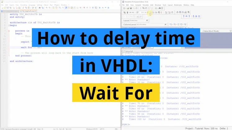
In this video tutorial we will learn how to create a procedure in VHDL:
The final code for the procedure testbench:
library ieee;
use ieee.std_logic_1164.all;
use ieee.numeric_std.all;

entity T19_ProcedureTb is
end entity;

architecture sim of T19_ProcedureTb is

    -- We're slowing down the clock to speed up simulation time
    constant ClockFrequencyHz : integer := 10; -- 10 Hz
    constant ClockPeriod : time := 1000 ms / ClockFrequencyHz;

    signal Clk     : std_logic := '1';
    signal nRst    : std_logic := '0';
    signal Seconds : integer;
    signal Minutes : integer;
    signal Hours   : integer;

begin

    -- The Device Under Test (DUT)
    i_Timer : entity work.T19_Timer(rtl)
    generic map(ClockFrequencyHz => ClockFrequencyHz)
    port map (
        Clk     => Clk,
        nRst    => nRst,
        Seconds => Seconds,
        Minutes => Minutes,
        Hours   => Hours);

    -- Process for generating clock
    Clk <= not Clk after ClockPeriod / 2;

    -- Testbench sequence
    process is
    begin
        wait until rising_edge(Clk);
        wait until rising_edge(Clk);

        -- Take the DUT out of reset
        nRst <= '1';

        wait;
    end process;

end architecture;
The final code for the timer module using a procedure:
library ieee;
use ieee.std_logic_1164.all;
use ieee.numeric_std.all;

entity T19_Timer is
generic(ClockFrequencyHz : integer);
port(
    Clk     : in std_logic;
    nRst    : in std_logic; -- Negative reset
    Seconds : inout integer;
    Minutes : inout integer;
    Hours   : inout integer);
end entity;

architecture rtl of T19_Timer is

    -- Signal for counting clock periods
    signal Ticks : integer;

    procedure IncrementWrap(signal   Counter   : inout integer;
                            constant WrapValue : in    integer;
                            constant Enable    : in    boolean;
                            variable Wrapped   : out   boolean) is
    begin
        Wrapped := false;
        if Enable then
            if Counter = WrapValue - 1 then
                Wrapped := true;
                Counter <= 0;
            else
                Counter <= Counter + 1;
            end if;
        end if;
    end procedure;

begin

    process(Clk) is
        variable Wrap : boolean;
    begin
        if rising_edge(Clk) then

            -- If the negative reset signal is active
            if nRst = '0' then
                Ticks   <= 0;
                Seconds <= 0;
                Minutes <= 0;
                Hours   <= 0;
            else

                -- Cascade counters
                IncrementWrap(Ticks, ClockFrequencyHz, true, Wrap);
                IncrementWrap(Seconds,             60, Wrap, Wrap);
                IncrementWrap(Minutes,             60, Wrap, Wrap);
                IncrementWrap(Hours,               24, Wrap, Wrap);

            end if;
        end if;
    end process;

end architecture;
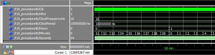
The waveform window in ModelSim zoomed in on the timeline where the Minutes signal is wrapping:
Need the Questa/ModelSim project files?
Let me send you a Zip with everything you need to get started in 30 seconds
Tested on Windows and Linux Loading Gif.. 
Analysis
We can see from the waveform that the wrapping of signals still works as it did in the previous tutorial. That’s because we haven’t actually changed the function on the module, only the way it’s implemented.
The first item on the parameter list for the IncrementWrap procedure is the Counter signal. It’s declared using direction inout for the procedure to be able to both read and set its value.
The second and third items on the parameter list are constants. This means that the values you put in here will appear as constants inside of the procedure. The WrapValue input together with the Enable input determines if the Counter signal is incremented or wrapped.
The last item on the parameter list is a variable with direction out. The purpose of this output is to inform the caller of the procedure that the counter wrapped. We use it here kind of like a return value.
In the main process we have four calls to the IncrementWrap procedure. Each of the subsequent calls use the Wrap variable to enable the counting. It wouldn’t have worked if we had used a signal instead of a variable, because signal values are only updated when a process goes to sleep. We need the output value from one procedure call to be be used as an input to a call on the very next line. Thus, it has to be a variable.
Get free access to the Basic VHDL Course
Download the course material and get started.
You will receive a Zip with exercises for the 23 video lessons as VHDL files where you fill in the blanks, code answers, and a link to the course.
By submitting, you consent to receive marketing emails from VHDLwhiz (unsubscribe anytime).
Takeaway
- Procedures can be used as mini-modules to avoid copy-pasting code
- Parameters (inputs/outputs) to a procedure can be signals, variables, or constants
- Unlike functions, procedures can contain wait-statements


@Jonas
Thank you for the tutorial.
Why do you need to double the `wait until rising_edge(Clk);` line in the test bench file?
Hi Kana,
Thank you for your curiosity.
I added a double rising_edge(Clk) in the testbench sequence to make the reset active for two full clock periods.
Here, I have zoomed in on the beginning of the waveform using the double rising_edge(Clk):
https://vhdlwhiz.com/wp-content/uploads/2018/10/two-clock-cycle-reset.png
First, the signals have default integer values. Then, at the first rising edge of the clock, the reset logic changes the values to 0. Finally, at the second rising edge of the clock, the reset signal is released.
Now consider the waveform where I have changed it to a single rising_edge(Clk):
https://vhdlwhiz.com/wp-content/uploads/2018/10/one-clock-cycle-reset.png
It still works. The rising edge of the clock triggers two things within the same timestep (delta cycle). The reset is released and at the same time the reset logic kicks in. The reset logic samples nRst which is still ‘0’ at the time. Therefore, the integer signals will appear to change at the same time as the reset is released.
I thought this might cause a bit of confusion, so I added another clock period to avoid the issue. Thereby adding another element of confusion 🙂
I should add that the reset signal is normally held for a number of clock period, not only one or two. This is known as a reset strobe.
Thanks Jonas, that’s very clear now, and I’ll check what strobes are used for.
Loved the tutorial series.. Do you have any plans to make advanced vhdl tutorial series? It will be helpful if you make a video on modelsim… Thanks again..
Glad you enjoyed the tutorials!
I am planning an intermediate VHDL course using FPGA development boards. I have also been thinking about teaching advanced testbench strategies. But a video only about ModelSim sounds like a good idea too. Thank you for the tip.
Jonas
Hi Sir Jonas!
Neat trick incrementing a variable that way. Is it possible to do the same method for incrementing an element in a multi dimensional array? Or is it better to assign the array element to a signal first?
I was wondering if there was more overhead trying to increment a array element directly as opposed to assigning it to a signal first..
Hi Dave,
You can increment an element within an array of integers by using the IncrementWrap procedure. All ways of incrementing integers are equally efficient. That’s because the FPGA never runs the code, your VHDL code describes a digital circuit. It will be the same circuit on the FPGA, no matter how you managed to describe it.
In the simulator, there may be some ways that are faster than others. I wouldn’t think about that. It’s more important to create code that works and is easy to understand.
You can convert the procedure to increment a member of the array like this:
subtype IntType is integer range 0 to 100;
type IntArrType is array (1 to 10) of IntType;

procedure IncrementWrap(signal Counters : inout IntArrType;
                        constant Index  : in integer) is
begin
  if Counters(Index) = IntType'high - 1 then
      Counters(Index) <= IntType'low;
  else
      Counters(Index) <= Counters(Index) + 1;
  end if;
end procedure;

signal Counters : IntArrType;
Or you can increment all elements within the integer array like this:
subtype IntType is integer range 0 to 100; type IntArrType is array (1 to 10) of IntType; procedure IncrementWrap(signal Counters : inout IntArrType) is begin for i in IntArrType'range loop if Counters(i) = IntType'high - 1 then Counters(i) <= IntType'low; else Counters(i) <= Counters(i) + 1; end if; end loop; end procedure;Thanks Jonas!
Highly appreciated and much more so that I could ever explain in a reply!
I will add it to my snippets and refer to it as needed. 🙂
@Jonas,
I believe that I found a minor error in the description of the following template:
procedure <procedure_name> (signal|variable|constant <name1> : in|out|inout <type>;
                            signal|variable|constant <name2> : in|out|inout <type>;
                            ... ) is
    <signal_constant_or_variable_declarations_for_use_within_the_procedure>
--        ^
-- note:  From what I can find, signal declarations inside a procedure body (after "is")
-- are not valid syntax.

begin
    <code_performed_by_the_procedure_here>
end procedure;
I could be wrong, but I cannot find any references to valid uses of signal declarations inside a procedure body.
They can be passed in, out, inout, but in all 3 cases, the signal is declared in an architecture.
For me, modelsim 10.5b barfs:”signal declaration ‘my_signal_name’ not allowed in this region.”
I wish this were permitted, as it would make overloading of procedures easier for my current project.
one workaround might be to declare the signal in an architecture of an entity, and pass it as an inout into the procedure.
It’s possible I’m incorrect. If so, please let me know / provide an example.
You are right, Kyle. That error has been in this article for a long time, but I’ve corrected it now. Thank you for making this blog better!
You can declare constants, variables, aliases, types, and subtypes inside of the procedure, but not signals.
why do you used tick signal and why do you check (tick = clkfreqHZ – 1) after the nRst is released
The Ticks signal is for counting clock cycles. I talked about it in an earlier video in this tutorial series. See the How to create a timer in VHDL video.
The ClockFrequencyHz constant stores the clock frequency of this circuit. Thus, to measure one second of real-time, we can count that many clock cycles. The minus one is because we are counting zero as well. To count exactly ClockFrequencyHz clock cycles, we have to compare with
ClockFrequencyHz - 1.When that happens, the IncrementWrap procedure resets the counter and sets the Wrapped output parameter to true.
Hello,
Jonas, this article its got a while and I think regardless the VHDL skill level still very useful like all the resources in this website, thanks for sharing.
Just made me thinking about the actual physical logic differences after implementation between functions and procedures… apart the wait feature, do you know if is there any other ‘significant’ differences between both, to take on account to decide between one or the other?
e.g. a procedure which uses a constant as input, will that create an extra flip flop to ‘lock’ the signal value till the internal operation is done and the function will use the same argument input register to perform that operation…?
I have seen some claims online that you shouldn’t use subprograms because they use more logic. I think that comes from a misunderstanding of how elaboration of VHDL code works.
Calling functions in regular programming languages may introduce a slight overhead because parameters and the return address are put on the stack. But when describing hardware with VHDL, there is no stack.
VHDL subprograms are more like “inline functions” in the C language. They are substituted for their content where they are called.
Whether a procedure generates a flip-flop or not depends on what the procedure contains, and not if the parameter is a constant, variable, or signal.
If the procedure contains a Wait Until or Wait On statement (like
wait until rising_edge(clk)), it will probably result in flip-flops being generated. That’s because time passes while we are in the procedure, and FPGAs use flip-flops to store data over time.Hi MR. Jensen,
A really odd thing happened when I ran this tutorial. Everything was fine right up until the last modifications. wave forms looked great. [Full disclosure, I am using the professional version of modelsim.] Below is my code. I’ve looked it over a couple of time and it looks perfect.
I’ve modified this to make for short simulations and quick debug. But I’m still at a loss.
But what happens is that when Seconds wraps, Minutes suddenly counts at tick rates for one Second then counts normally until seconds warps again. Then minutes does the same thing. then hrs when minutes wraps.
Could it be a bug in my version of modelsim?
Thanks,
Bill
T19a_ProcedureTb.vhd:
T19a_Timer.vhd:
Hello William,
I have reviewed your example, but it has nothing to do with the changes you made because the error is also present in my original code.
It worked correctly in the older student edition of ModelSim, but it doesn’t work in QuestaSim.
It’s because of how I wrote this procedure:
procedure IncrementWrap(signal   Counter   : inout integer;
                        constant WrapValue : in    integer;
                        constant Enable    : in    boolean;
                        variable Wrapped   : out   boolean) is
begin
    if Enable then
        if Counter = WrapValue - 1 then
            Wrapped := true;
            Counter <= 0;
        else
            Wrapped := false;
            Counter <= Counter + 1;
        end if;
    end if;
end procedure;
Notice that it doesn’t alter the
Wrappedvariable ifEnableisfalse. That’s wrong because it means it remains untouched at whatever value it got from the previous call to this procedure.It appears that the older ModelSim version defaulted to setting the
Wrappedoutput from the procedure tofalsewhile Questa doesn’t do that.I don’t know which is correct according to the VHDL language reference manual. I will try to find out later.
The fix is to move the
Wrapped := false;assignment outside of the If statement and use it as a default value like this:procedure IncrementWrap(signal Counter : inout integer; constant WrapValue : in integer; constant Enable : in boolean; variable Wrapped : out boolean) is begin Wrapped := false; if Enable then if Counter = WrapValue - 1 then Wrapped := true; Counter <= 0; else Counter <= Counter + 1; end if; end if; end procedure;I have updated the blog post and the downloadable examples, but unfortunately, I can’t change the video.
Thanks for reporting the bug!
hello!
thanks for your good website
i cant use a type that i have defined in my program
it means in vhdl procedure we cant use personal type that we have defined and should be use just std_logic and ………..?
You can use any type as long as the type declaration is visible to the procedure. If you want to use the same type declaration in several VHDL files, you can put it in a VHDL package that you import into every other VHDL file.
Hi! This code does not work. When Wrap become “1” , next procedure “IncrementWrap..” does not see this “1”… In my case, I do not know why…
There was a bug in the code shown in the video that I have since corrected. I have updated the code in the blog post and the downloadable. Unfortunately, I can’t change the video on YouTube.
The problem was that after we added the Enable signal, we should have moved the Wrapped := false; outside of the if Enable like this:
procedure IncrementWrap(signal Counter : inout integer; constant WrapValue : in integer; constant Enable : in boolean; variable Wrapped : out boolean) is begin Wrapped := false; if Enable then if Counter = WrapValue - 1 then Wrapped := true; Counter <= 0; else Counter <= Counter + 1; end if; end if; end procedure;It worked in earlier versions of ModelSim, but it really shouldn’t have. It was wrong.