A finite-state machine (FSM) is a mechanism whose output is dependent not only on the current state of the input, but also on past input and output values.
Whenever you need to create some sort of time-dependent algorithm in VHDL, or if you are faced with the problem of implementing a computer program in an FPGA, it can usually be solved by using an FSM.
State machines in VHDL are clocked processes whose outputs are controlled by the value of a state signal. The state signal serves as an internal memory of what happened in the previous iteration.
This blog post is part of the Basic VHDL Tutorials series.
Consider the states of the traffic lights at this intersection:
The traffic lights have a finite number of states, which we have given identifiable names. Our example state machine has no controlling inputs, the output is the state of the lights in north/south and west/east directions. It is elapsed time and the previous state of outputs which advances this state machine.
We can represent states in VHDL using an enumerated type. These are data types just like signed or unsigned, but instead of integer numbers, we can supply a custom list of possible values. In fact, if you take a look in the std_logic_1164 package, you will find that the std_ulogic type is nothing more than an enumerated type with the values 'U', 'X', '0', '1', 'Z', 'W', 'L', 'H', and '-' listed as enumeration values.
Once we have our enumerated type, we can declare a signal of the new type, which can be used for keeping track of the FSM’s current state.
The syntax for declaring a signal with an enumerated type in VHDL is:
type <type_name> is (<state_name1>, <state_name2>, ...);
    signal <signal_name> : <type_name>;
Using the state signal, the finite-state machine can then be implemented in a process with a Case statement. The Case statement contains a When statement for each of the possible states, causing the program to take different paths for every state. The When statement can also contain code that should be executed while in that particular state. The state will then typically change when a predefined condition is met.
This is a template for one-process state machine:
process(Clk) is
begin
    if rising_edge(Clk) then
        if nRst = '0' then
            State <= <reset_state>;
        else
            case State is
                when <state_name> =>
                    <set_outputs_for_this_state_here>
                    if <state_change_condition_is_true> then
                        State <= <next_state_name>;
                    end if;
                ...
            end case;
        end if;
    end if;
end process;
Note:
There are several ways to create an FSM in VHDL. Read about the different styles here:
One-process vs two-process vs three-process state machine
Exercise
In this video tutorial, we will learn how to create a finite-state machine in VHDL:
The final code for the state machine testbench:
library ieee;
use ieee.std_logic_1164.all;
use ieee.numeric_std.all;

entity T20_FiniteStateMachineTb is
end entity;

architecture sim of T20_FiniteStateMachineTb is

    -- We are using a low clock frequency to speed up the simulation
    constant ClockFrequencyHz : integer := 100; -- 100 Hz
    constant ClockPeriod : time := 1000 ms / ClockFrequencyHz;

    signal Clk         : std_logic := '1';
    signal nRst        : std_logic := '0';
    signal NorthRed    : std_logic;
    signal NorthYellow : std_logic;
    signal NorthGreen  : std_logic;
    signal WestRed     : std_logic;
    signal WestYellow  : std_logic;
    signal WestGreen   : std_logic;

begin

    -- The Device Under Test (DUT)
    i_TrafficLights : entity work.T20_TrafficLights(rtl)
    generic map(ClockFrequencyHz => ClockFrequencyHz)
    port map (
        Clk         => Clk,
        nRst        => nRst,
        NorthRed    => NorthRed,
        NorthYellow => NorthYellow,
        NorthGreen  => NorthGreen,
        WestRed     => WestRed,
        WestYellow  => WestYellow,
        WestGreen   => WestGreen);

    -- Process for generating clock
    Clk <= not Clk after ClockPeriod / 2;

    -- Testbench sequence
    process is
    begin
        wait until rising_edge(Clk);
        wait until rising_edge(Clk);

        -- Take the DUT out of reset
        nRst <= '1';

        wait;
    end process;

end architecture;
The final code for the state machine module:
library ieee;
use ieee.std_logic_1164.all;
use ieee.numeric_std.all;

entity T20_TrafficLights is
generic(ClockFrequencyHz : integer);
port(
    Clk         : in std_logic;
    nRst        : in std_logic; -- Negative reset
    NorthRed    : out std_logic;
    NorthYellow : out std_logic;
    NorthGreen  : out std_logic;
    WestRed     : out std_logic;
    WestYellow  : out std_logic;
    WestGreen   : out std_logic);
end entity;

architecture rtl of T20_TrafficLights is

    -- Enumerated type declaration and state signal declaration
    type t_State is (NorthNext, StartNorth, North, StopNorth,
                        WestNext, StartWest, West, StopWest);
    signal State : t_State;

    -- Counter for counting clock periods, 1 minute max
    signal Counter : integer range 0 to ClockFrequencyHz * 60;

begin

    process(Clk) is
    begin
        if rising_edge(Clk) then
            if nRst = '0' then
                -- Reset values
                State   <= NorthNext;
                Counter <= 0;
                NorthRed    <= '1';
                NorthYellow <= '0';
                NorthGreen  <= '0';
                WestRed     <= '1';
                WestYellow  <= '0';
                WestGreen   <= '0';

            else
                -- Default values
                NorthRed    <= '0';
                NorthYellow <= '0';
                NorthGreen  <= '0';
                WestRed     <= '0';
                WestYellow  <= '0';
                WestGreen   <= '0';

                Counter <= Counter + 1;

                case State is

                    -- Red in all directions
                    when NorthNext =>
                        NorthRed <= '1';
                        WestRed  <= '1';
                        -- If 5 seconds have passed
                        if Counter = ClockFrequencyHz * 5 -1 then
                            Counter <= 0;
                            State   <= StartNorth;
                        end if;

                    -- Red and yellow in north/south direction
                    when StartNorth =>
                        NorthRed    <= '1';
                        NorthYellow <= '1';
                        WestRed     <= '1';
                        -- If 5 seconds have passed
                        if Counter = ClockFrequencyHz * 5 -1 then
                            Counter <= 0;
                            State   <= North;
                        end if;

                    -- Green in north/south direction
                    when North =>
                        NorthGreen <= '1';
                        WestRed    <= '1';
                        -- If 1 minute has passed
                        if Counter = ClockFrequencyHz * 60 -1 then
                            Counter <= 0;
                            State   <= StopNorth;
                        end if;

                    -- Yellow in north/south direction
                    when StopNorth =>
                        NorthYellow <= '1';
                        WestRed     <= '1';
                        -- If 5 seconds have passed
                        if Counter = ClockFrequencyHz * 5 -1 then
                            Counter <= 0;
                            State   <= WestNext;
                        end if;

                    -- Red in all directions
                    when WestNext =>
                        NorthRed <= '1';
                        WestRed  <= '1';
                        -- If 5 seconds have passed
                        if Counter = ClockFrequencyHz * 5 -1 then
                            Counter <= 0;
                            State   <= StartWest;
                        end if;

                    -- Red and yellow in west/east direction
                    when StartWest =>
                        NorthRed   <= '1';
                        WestRed    <= '1';
                        WestYellow <= '1';
                        -- If 5 seconds have passed
                        if Counter = ClockFrequencyHz * 5 -1 then
                            Counter <= 0;
                            State   <= West;
                        end if;

                    -- Green in west/east direction
                    when West =>
                        NorthRed  <= '1';
                        WestGreen <= '1';
                        -- If 1 minute has passed
                        if Counter = ClockFrequencyHz * 60 -1 then
                            Counter <= 0;
                            State   <= StopWest;
                        end if;

                    -- Yellow in west/east direction
                    when StopWest =>
                        NorthRed   <= '1';
                        WestYellow <= '1';
                        -- If 5 seconds have passed
                        if Counter = ClockFrequencyHz * 5 -1 then
                            Counter <= 0;
                            State   <= NorthNext;
                        end if;

                end case;

            end if;
        end if;
    end process;

end architecture;
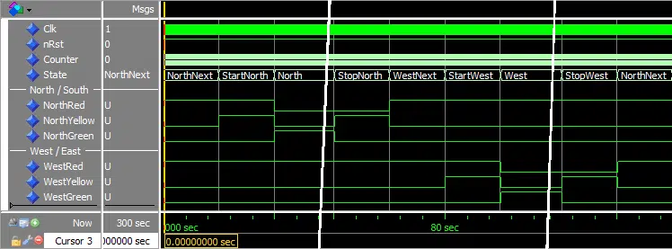
The waveform after we entered the run 5 min command in the ModelSim console:
Need the Questa/ModelSim project files?
Let me send you a Zip with everything you need to get started in 30 seconds
Tested on Windows and Linux Loading Gif.. 
Analysis
We declared an enumerated type with all the eight different states of our traffic lights. Then, we declared a state signal of this new type that we created. This means that the signal can only have one of the eight named state values and no other values.
The FSM was implemented using a Case-statement within a clocked process. On each rising edge of the clock, the process wakes up, and the state signal is evaluated. The code within exactly one of the when choices (branches) is allowed to run, depending on the current state.
In our code, it is the value of the Counter signal that triggers state changes. When the Counter reaches a predefined value, representing 5 seconds or 1 minute, a new state encoding is assigned to the State signal. Then, when the process wakes up on the next rising edge of the clock after the state value has been updated, the FSM is in a different state.
Note that we are not assigning '0' to any signal in any of the when choices. This is because we have given all the output signals a default value of '0' at the beginning of the process. You may remember from a previous tutorial that it is the last value which is assigned to a signal that becomes effective. Signal assignments become effective only after the process terminates. If we assign '0' to the signal at the beginning of the process, and then '1' in one of the when choices, the signal will get the value '1'.
We can see from the waveform that the State signal cycles through the eight states. The steady green states last for one minute, the waveform image has therefore been cut in the North and West states.
Get free access to the Basic VHDL Course
Download the course material and get started.
You will receive a Zip with exercises for the 23 video lessons as VHDL files where you fill in the blanks, code answers, and a link to the course.
By submitting, you consent to receive marketing emails from VHDLwhiz (unsubscribe anytime).
Takeaway
- Algorithms are usually implemented as finite-state machines (FSMs)
- An FSM can be implemented by using a case statement in a clocked process
- FSM states can be implemented in an enumerated type


Hi, I am absolutely beginner in VHDL and FPGA and I’ve tried to run your Finite State Machine code in Quartus II, but it didn’t work at all. Errors are everywhere, for example that there can not be more than one wait statement in process like “wait until rising_edge(Clk);”
Is it because of the Quartus II?
Hi John,
I think the problem is that to simulate through Quartus, you have to synthesize the code as an RTL module before you can start the simulation. The examples in this tutorial series are not synthesizable, and therefore, it fails with the error you are describing.
Instead, start ModelSim or whichever simulator you are using independent from Quartus. For ModelSim, that would be the “vsim” command found in the modelsim* folder.
You may want to start at the beginning of the Basic VHDL Tutorials series to learn how to set up a project in ModelSim correctly.
Hi . Pllz can you tell how to create this code on quartus
Hello, Imane. The VHDL code is generic and works in any capable VHDL simulator. You should download the free Quartus-Intel edition, the updated version of the ModelSim simulator. Quartus is an FPGA implementation tool, but that’s not what you need for running this code. You need to get a simulator like Questa or ModelSim.
Ok thank u Mr jonas , how can I contact u pllz ? Have an email ?
I don’t do private tutoring via email. But perhaps you are interested in joining the private Facebook group where you can ask questions and chat with thousands of members: VHDL for FPGA Engineers.
In your little GIF animation of stop lights you have the phase wrong.
https://vhdlwhiz.com/wp-content/uploads/2016/11/intersection_fsm.gif
Everybody is driving through red lights.
Is this animation based on the USA?
Haha, I see what you mean. You are thinking that the lights are suspended horizontally above the road, as they are in the US. What I meant to show is the lights mounted vertically on a pole at the sides of the intersection. That’s how they are in Europe and in Norway where I’m from.
Hi. I copied the code which you uploaded and did the same things with you in modelsim. But when I simulate the code, state remains at ‘NorthNext’ state and never changes. Where did I wrong? How can I fix it ?
Hello Bengü,
I’m not sure why you’re not getting the same results. Probably you are doing something different from what I did.
Maybe you should download the example project instead of copy-pasting the code. You can request the Zip file by entering your email address in the form that says “Need the ModelSim project files?” on this page.
Refer to the “How to run.txt” file for instructions on how to run the simulation.