Most of us stick to a certain way of writing a state machine. Perhaps you type out the construct that you are most familiar with without giving much thought to the alternatives. Depending on the method that you were taught when learning VHDL, you may prefer one method to another.
Over the years, I have seen many different state machine designs. To appease my curiosity, I set out to investigate the most common ways to design finite-state machines (FSMs) in VHDL. As it turns out, there are actually quite a few ways to write them.
The most apparent difference between FSMs written in VHDL, is the number of processes used. The FSM may be implemented entirely in one clocked process. Or it can be split up into one synchronous process and one or two combinatorial processes. Namely the two-process or three-process state machine.
The number of processes is not the only thing that sets FSM designs apart. They can also be divided into two different behavior types; Mealy and Moore machines. As we shall see, some designs can be used for both, while others are restricted to implementing Moore machines.
The testcase
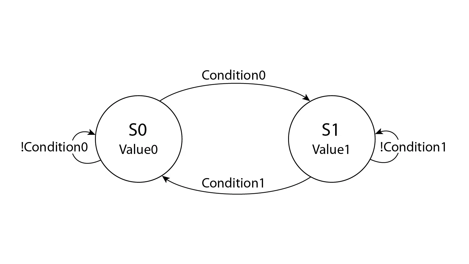
We are going to implement this state machine diagram in the subsequent sections:

The FSM consists of two states; S0 and S1. The output value in each state is denoted below the state names; Value0 and Value1. The vertices represent state changes, and the text on the vertices are boolean conditions that will cause the FSM to take that path. They are simply named Condition0 and Condition1.
Assume that Value0 and Value1 are constants.
One-process state machine
The one-process FSM design is the one you are most likely to encounter. It is usually implemented as a fully synchronous process. This results in the state, as well as the output being implemented in registers.
Learn how to create a traffic lights controller using a one-process FSM!
An advantage is that synchronous designs usually are easier to debug. Depending on the enclosing logic, it could also make it easier to meet timing requirements during place and route.
Below is a one-process implementation of the FSM.
process(Clk) is
begin
   if rising_edge(Clk) then
       if nRst = '0' then
           State <= S0;
           Dout  <= Value0;

       else

           case State is

               when S0 =>
                   Dout <= Value0;

                   if Condition0 then
                       State <= S1;
                   end if;

               when S1 =>
                   Dout <= Value1;

                   if Condition1 then
                       State <= S0;
                   end if;

           end case;
       end if;
   end if;
end process;
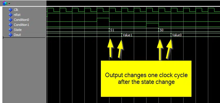
A consequence of setting the output within the state that it belongs to, is that the output signal will change one clock cycle after the state signal. This is generally not a problem when it comes to the function of the FSM. But as we can see from the waveform below, it can be a little confusing to make sense of during a debugging session.
Mealy and Moore
FSMs can generally be divided into two types; Mealy machines and Moore machines. All of the above belong to the latter. The FSM diagram, the VHDL code, and the waveform are all related to the Moore machine.
The Mealy and Moore machines are named after their creators. They were thought out long before any FPGAs ever existed. The concept of state machines is universal, but comes very handy when describing the behavior of digital logic.
Mealy can do more than Moore
The difference between a Mealy machine and a Moore machine is how and when the outputs are changed. In a Moore machine, the outputs are set based on the current state. In a Mealy machine on the other hand, the outputs are set when the state change happens.
Consider this example which is the one-process state machine from the top of this article converted into a Mealy type state machine:
process(Clk) is
begin
   if rising_edge(Clk) then
       if nRst = '0' then
            State <= S0;
            Dout  <= Value0;

       else

           case State is

               when S0 =>
                   if Condition0 then
                       State <= S1;
                       Dout  <= Value1;
                   end if;

               when S1 =>
                   if Condition1 then
                       State <= S0;
                       Dout  <= Value0;
                   end if;

           end case;
       end if;
   end if;
end process;
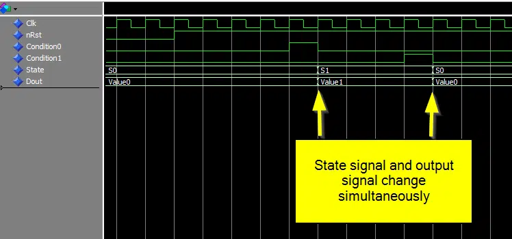
The assignment to the output signal Dout has been moved inside of the If-statement. At the same time, the State signal is changed. One advantage of this can be viewed in the waveform below. The state and output signals change simultaneously. Thus, making debugging easier.
State machine diagrams for Mealy machines are usually drawn differently than for Moore machines. While the diagram shown earlier in this article was a Moore type diagram, this is the equivalent Mealy type diagram:

The notation on the vertices is on the format input / output.
Using Mealy machines sometimes result in state machines with fewer states than a Moore machine would require. This is because they can eliminate the need for some transitional states.
Two-process state machine
Some engineers prefer to divide the FSM code into two processes. One synchronous, and the other combinatorial. To add to the confusion, there are at least three different ways that a two-process state machine can be implemented.
Sequential process controls current State
In this implementation, a NextState signal exists in addition to the usual State signal. The synchronous process only controls the State signal. All other related signals are set by the combinatorial process as a result of a changed state or condition.
process(Clk) is
begin
    if rising_edge(Clk) then
        if nRst = '0' then
            State <= S0;

        else
            State <= NextState;

        end if;
    end if;
end process;

process(State, Condition0, Condition1) is
begin
    NextState <= State;

    case State is

        when S0 =>
            Dout <= Value0;

            if Condition0 then
                NextState <= S1;
            end if;

        when S1 =>
            Dout <= Value1;

            if Condition1 then
                NextState <= S0;
            end if;

    end case;
end process;
Although this is a Moore machine, the state signal will be aligned with the output signal. This is due to the extra NextState signal which is set by the combinatorial process. In the waveform below we can see that the State and Dout signals are in sync, and the NextState signal precedes them by one clock cycle.
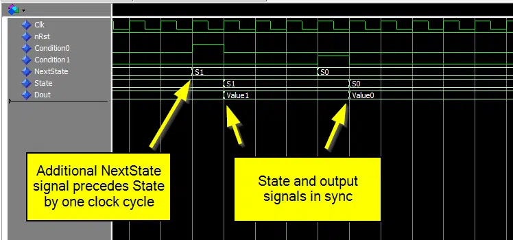
Another thing to be aware of is that although the output and state signals are synchronous in time, the output will be delayed by one delta cycle. As we can see from the waveform below, Dout changes one delta cycle after the State signal.
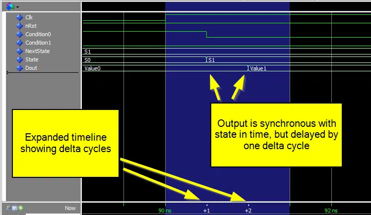
A delta cycle is a zero-time unit used by VHDL simulators to model changes in signal values in combinatorial processes. Depending on the logic in the downstream data path, this may affect the synthesized netlist. Or it may cause the behavior in simulation to differ from the behavior of the implemented design. There is nothing magical or mystical about delta cycles, but that is out of the scope of this article.
Read more about delta cycles here
Sequential process controls state
In this variant of the two-process state machine, there is no NextState signal. The sequential process entirely controls the State signal. The combinatorial process is sensitive to state changes, and sets the output signal accordingly.
process(Clk) is
begin
    if rising_edge(Clk) then
        if nRst = '0' then
            State <= S0;

        else
            case State is

                when S0 =>
                    if Condition0 then
                        State <= S1;
                    end if;

                when S1 =>
                    if Condition1 then
                        State <= S0;
                    end if;

            end case;

        end if;
    end if;
end process;

process(State) is
begin
    case State is

        when S0 =>
            Dout <= Value0;

        when S1 =>
            Dout <= Value1;

    end case;
end process;
This is also a Moore type state machine because the output is set based on the active state. While state and output signals will appear to be in sync in the waveform, the output is in fact delayed by a delta cycle.
Sequential process controls current state and output
Here, we are letting the synchronous process control the current state signal as well as the output signal. This implementation is logically equivalent to the Moore type one-process FSM mentioned at the beginning of this article.
process(Clk) is
begin
    if rising_edge(Clk) then
        if nRst = '0' then
            State <= S0;
            Dout  <= Value0;

        else
            State <= NextState;

            case State is

                when S0 =>
                    Dout <= Value0;

                when S1 =>
                    Dout <= Value1;

            end case;
        end if;
    end if;
end process;

process(State, Condition0, Condition1) is
begin
    NextState <= State;

    case State is

        when S0 =>
            if Condition0 then
                NextState <= S1;
            end if;

        when S1 =>
            if Condition1 then
                NextState <= S0;
            end if;

    end case;
end process;
By synchronizing both the state and output signal to the clock, we can ensure that they will be implemented in registers, regardless of how the downstream logic looks like. Also, there is no delta cycle delay between the state and output signals.
The choice between using the one-process FSM or this two-process equivalent is entirely down to preference. Some people think that factoring out the state changing code into a combinational process looks better. Others believe that splitting things that belong together and the extra NextState signal just makes it more complicated.
Three-process state machine
Some engineers prefer to split up code into as many processes as possible. Every signal would have its own process if possible. There certainly are advantages to this divide and conquer strategy. A process is a design unit, and it makes sense to make them as specialized as possible.
process(Clk) is
begin
    if rising_edge(Clk) then
        if nRst = '0' then
            State <= S0;

        else
            State <= NextState;

        end if;
    end if;
end process;

process(State) is
begin
    case State is

        when S0 =>
            Dout <= Value0;

        when S1 =>
            Dout <= Value1;

    end case;
end process;

process(State, Condition0, Condition1) is
begin
    NextState <= State;

    case State is

        when S0 =>
            if Condition0 then
                NextState <= S1;
            end if;

        when S1 =>
            if Condition1 then
                NextState <= S0;
            end if;

    end case;
end process;
This Moore type FSM uses next state logic. Therefore the State and Dout signals will appear to be in sync, while the Dout signal is in reality delayed by a delta cycle. It is essentially the same as the first two-process FSM mentioned in this article, but the output signal now has its own combinatorial process.
Which one should you use?
There is no right or wrong. It depends on a number of things. Do you need a Moore machine or a Mealy machine? Is the downstream logic that received the output signal synchronous or combinatorial? It also depends on which style of coding you prefer.
The one-process FSM is probably the most common type. But you will definitely encounter FSMs using multiple processes if you haven’t already.
I have found that preference for one type or the other sometimes depend on the background of the person. Engineers that have a computer science background, like I do, are more likely to choose the one-process FSM. Perhaps because they are used to thinking in a sequential manor when analyzing code.
Similarly, engineers that have an electronics background are more likely to use a two- or three-process FSM. Older, more experienced individuals, are more likely to prefer multi-process variants (perhaps we should listen to them).
These are of course entirely my subjective observations.
Whichever style you choose, make sure you so with Moore/Mealy machines and delta cycles in mind.


Dear Jonas
Hi,
Thanks for sharing, It’s inspiring and very helpful.
Please keep u the nice work.
Best Regards
Thank you!
I’m glad you found the blog post helpful. Let me know if there is something in particular you would like to see an article about.
Jonas
Regarding the one-process state machine, have you considered storing the state vector in a process variable?
    example_fsm : process(clock, reset)
        variable state      : fsm_type;
        variable next_state : fsm_type;
    begin
        if ((reset = RST_ACT_LVL) and (ASYNC_RST)) then
        test <= parity(test);

        elsif(rising_edge(clock)) then
            if ((reset = RST_ACT_LVL) and (not(ASYNC_RST))) then

            else
                -- State case
                case(state) is
                    when IDLE =>
                        next_state := STATE1;

                    when STATE1 =>
                        next_state := IDLE;

                    when others =>
                        null;
                end case;

                -- Commands
                ---------------------------
                -- Command description:
                -- Transitions :
                -- IDLE to STATE1
                ---------------------------
                if ((state = IDLE) and (next_state = STATE1)) then
                    null;

                end if;


                -- State progression
                state := next_state;
            end if;
        end if;
    end process example_fsm;
I feel like this method eliminates the discrepancy between signal and state value while keeping the other one-process-fsm advantages.
That’s definitely a valid solution for a one-process FSM. I didn’t think of it because I generally try to avoid using variables in such a way that they result in registers. There’s nothing wrong with doing so, it’s just down to coding style. I’ve gone back and forth with this over the years 🙂
A drawback of using variables for registers is that it can be difficult to predict what kind of hardware it will synthesize into, although in this example, it’s pretty clear. Also, they can be a bit harder to work with in the simulator. Not showing up in waveforms by default, etc.
On the plus side, it’s nice to be able to encapsulate objects that belong to the process inside of it. You could do that with the state type as well.
Please explain more about the sensitivity list of the FSM machine in this article. How the constants of conditions 0 and 1 are assigned.
Thank you.
Hello Elik,
Condition0 and Condition1 are boolean expressions. The code below shows an example of what it could mean.
However, I just used the placeholders in this article for simplicity. For any practical purpose, I would ditch the boolean signals and use the ones behind them in the FSM process, like in the example below.
process(State, rx, rx_prev, ..) is begin NextState <= State; case State is when S0 => if rx = '1' and rx_prev = '0' then NextState <= S1; end if;Does this two or three process also helps to develop the FSM for 3-way handshaking protocol part of TCP? Actually I am trying to design it using a sequence detector, so if any idea kindly share.
Hello Komal,
I would go for a one-process Mealy type state machine to implement the main control logic. Because in the 3-way handshake, you wait for incoming data (SYN). When you receive it, you send a response (SYN+ACK), and then immediately go on to wait for the next event (ACK). The output happens when you change from one state to the next, which is the Mealy behavior.
However, you will likely need more than one state machine. Perhaps you can have one that controls the main control flow, one that receives data and decodes packages, and one that transmits data.
But there are a thousand ways to implement this. If you have another idea in mind, just try it out.
I have found there are times where using a single synchronous state machine just won’t work for a given task. An example that comes to mind is implementing reads on block RAM ( I’m thinking Xilinx Block RAM here). Despite this fact, I typically prefer to try and implement single ( or multiple ) synchronous state machines whenever i can.
With synchronous state machines, as long as timing is met during implementation, the design will 99.9999999% of the time work properly in hardware. This of course assumes that clocks are properly constrained, this is typically automated by compilers now a days. In large designs that utilize a lot of synchronous / asynchronous state machines, the asynchronous signals are not explicitly constrained, and during implementation, the router is free to do what it wants, as a consequence, your design could work perfectly well, you make one small change, re-synthesis, and re-implement, the router will will route the signals differently, which could lead to a different result in hardware. This can be very difficult to troubleshoot!
Thank you for the insightful comment, Brandon. It can indeed be troublesome when you have deep logic with state machines that depend on each other.
I know this is an old article but as an older experienced electronic engineer I have to say that experience tends to push you toward the single process solution (as preferred by SW engineers). In my experience it is only graduates and academics that use a multiprocess FSM style.
Multi process FSM implementations suffer from several problems, the main ones are:
1. It is very easy to accidentally infer a latch in your design. You almost never want that.
2. Distribution logic across processes makes it harder to keep track of what is going on which makes the code harder to understand, debug, and maintain. This is super important because you will be back to fix or modify your code at some point in the future, or worse some other poor developer will have to do it.
3. It is easy to get a Mealy machine when you generally want a Moore machine. If you need a Mealy machine, have a separate combinatorial process for the Mealy signals to highlight this fact as Mealy machines can lead unforseen timing closure problems.
Hello Thomas,
It’s old but still relevant. ?
Thank you for the insightful comment!
I see your points. These days I prefer to put everything in one process. But I have to admit that my preference has gone back and forth several times over the years.
Hi Jonas,
thanks for your inspiring blogs! In your 3rd example of the 2-process state machines (“Sequential process controls current state and output”) in line 11 you use ‘State’ for your case statement:
State <= NextState;

case State is

  when S0 =>
    Dout <= Value0;

  when S1 =>
    Dout <= Value1;

end case;
You write that there is no delta cycle between the state and the output signals. But as you're inside a clocked process you'd have a complete clock cycle between the State and the output values, wouldn't you? This could be easily avoided by using 'NextState' for your case statement. Isn't that what you intended to do:
State <= NextState; case NextState is when S0 => Dout <= Value0; when S1 => Dout <= Value1; end case;Sure, you can do that too. If we case on NextState, it would be equivalent to the one-process Mealy machine, at least in simulation.
Good catch! 😎
you posted
process(Clk) is
begin
    if rising_edge(Clk) then
        if nRst = '0' then
            State <= S0;

        else
            State <= NextState;

        end if;
    end if;
end process;

process(State, Condition0, Condition1) is
begin
    NextState
            Dout <= Value0;

            if Condition0 then
                NextState
            Dout <= Value1;

            if Condition1 then
                NextState <= S0;
            end if;

    end case;
end process;
if im in S0, and Value0 changes, id be expecting output to change, but Value0 is not in your sensetivity list !
Hello, Andrews. Thanks for commenting! At first, when I read your comment, I thought, “Oh dear, I messed up. How did that slide for many years?”
Because if they were all signals, they should definitely be on the sensitivity list. Any signal whose value is used (read/copied/evaluated) must be on the sensitivity list of a combinational process. A clocked process, on the other hand, needs only the clock (and reset if using async reset).
BUT, at the beginning of this article, I wrote: “Assume that Value0 and Value1 are constants.” In that case, they don’t need to be on the sensitivity list since constants never change.
I want to give you credit for calling this out because that’s not obvious at all. If I were going to rewrite the article, I would instead use the VHDL-2008 “all” keyword that catches any signal that’s used in the process: