
A latch is a logic element that can sample and hold a binary value, much like a flip-flop (register). But unlike a flip-flop, which is edge-triggered, the latch is level-triggered.
To memorize how the digital latch works you can think of the door locking mechanism that it’s named after, shown in the example photo.
While the bolt is retracted, the door will open and anything can pass through. But as soon as we push the bolt into the receptacle, it locks the door.
How a transparent D latch works
A digital latch works much like its analog counterpart. When open, it will let the input value pass through to the output, and when closed, it will lock in whatever value was already being forwarded.
According to the Modeling Latches and Flip-Flops document from Xilinx, the schematic below describes the behavior of a D latch in their FPGAs. The naming convention comes from the data input, often denoted as D.
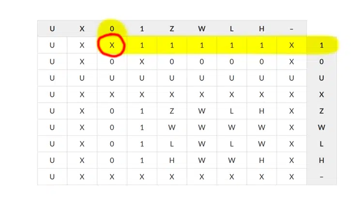
Observe the values as they change in the logic gate animation. If you pay attention, you will notice that the value on the D input propagates to the Q output only when the E (Enable) input is ‘1’.
| E | D | Q |
|---|---|---|
| 1 | 1 | 1 |
| 1 | 0 | 0 |
| 0 | 1 | Latched D value |
| 0 | 0 | Latched D value |
We can say that the latch is transparent as long as the enable input is active. It’s as if the latch wasn’t there. That’s why the D latch is often called a transparent latch.
When we assign ‘0’ to the E input, the Q output will stop reacting to changes on D. The value is frozen, or latched, until we set E to ‘1’ again.
The truth table for the transparent latch is comparable to that of a flip-flop without reset. But the latch samples the value on the falling edge of the Enable input. And it lets the input propagate during the high period of the Enable (usually the clock), while the flip-flop doesn’t.
How to infer a latch with VHDL
If you really want a latch, this is how to create one:
process(enable, d)
begin
  if enable = '1' then

    q <= d;

  end if;
end process;
But most latches are accidentally inferred because there’s something wrong with your VHDL process.
The code below shows a typical accidental latch inference. The designer probably wanted to create an edge-sensitive process, but forgot to use if clk'event and clk = '1' then or if rising_edge(clk) then.
process(clk)
begin
  if clk = '1' then

    q <= d;

  end if;
end process;
When synthesized in Vivado, the code produces the familiar “[Synth 8-327] inferring latch for variable XX” warning, accompanied by “[Synth 8-614] signal XX is read in the process but is not in the sensitivity list“.
![[Synth 8-614] signal 'd' is read in the process but is not in the sensitivity list. [Synth 8-327] inferring latch for variable 'q_reg'](https://cdn.vhdlwhiz.com/wp-content/uploads/2020/11/Inferring-latch-Vivado.png.webp)
And similarly, Intel Quartus will say “Info (10041): Inferred latch for XX at YY“, as shown in the image below.

Another common error that will result in latches is to forget the Else clause in a combinational process. The example below may produce a latch because data_out is not given a value when read_data is ‘0’.
process(read_data, fifo_out)
begin
  if read_data = '1' then

    data_out <= fifo_out;

  end if;
end process;
The solution is to add an Else clause to the If statement. If we assign something to the output for all possible combinations of the control signals, it won’t generate latches.
What’s the problem with latches?
The synthesis tool will warn you about latches because there’s no reason to have them. I’ve never needed a latch in my career. Please let me know in the comment section if you see any use cases for latches.
Latches essentially do the same thing as flip-flops, but with inferior timing capabilities. Study the illustration shown below to see what I mean.
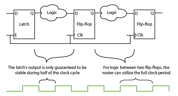
In the first half of the example, we have a latch whose output goes through combinational logic to a flip-flop.
We don’t know what comes before the latch, and therefore we must assume that its input can change at any time. The only time the latch output is stable is during the low half period of the clock cycle.
The latch gives the place and route tool less flexibility to meet timing.
In the second half of the schematic, the combinational logic is between two flip-flops. Because both flip-flops sample the data input instantaneously, the signal has the full clock period to propagate through the combinational logic.
Furthermore, the FPGA implements both latches and flip-flops using the same configurable register primitives. We can see evidence of this in the resources utilization report from Vivado, shown below.
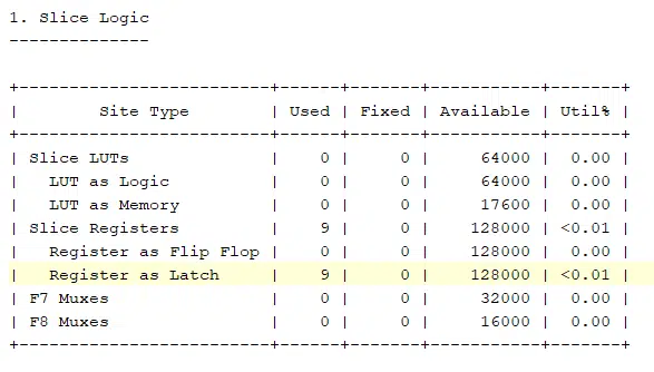
A latch doesn’t save logic resources in the FPGA because it uses the same primitive as a flip-flop.
While your logic may work well with latches, they are probably not what you want. Latches put strains on the router and offer no added benefit compared to flip-flops.

Yes, I have used it frequently for flight test vehicles. Some situations require a permanent (reset on power-up) or temporary (special reset sequence) latch. But, in the case described above it was used in a design of GPS (Global Positioning System) and EVS (Enhanced Vision System). Certain times the unwanted thing behavior can be used to advantage.
Thank you for sharing a real-world use case for latches in FPGAs!
Hi Jonas.
Might sound silly, but as a hardware developer I have many times needed to let an Address but go through a Latch to let it through, and “lock” it when the latch was disabled. A Flip-Flop cannot do that, It will not pass through before clocked.
Well, yes. Just because I couldn’t come up with an example, it doesn’t mean there are zero use cases for latches.
Thanks for sharing! ?
😀 :D.
To implement asynchronous FSM in VHDL, we have to use lathces, am i wrong?
I’m not sure because I’ve never created one. 🙂 I try to avoid asynchronous logic as much as possible because it’s difficult to design and debug.
Latches are handy in case you need to save power and/or area, since they require less transistors to be implemented.
The propagation time is also lower then that of a FF.
I believe that’s true for ASIC design, but in FPGAs, it’s the same primitives configured as FFs or latches.
Thank you for commenting! 🙂
hello jonas,
we checked and this code indeed create a FF!!
We checked the code in quartus16.1 and quartus18.1 and we saw that the synthesis tool does produce FF !! why? thanks
process(clk) begin if clk = '1' then q <= d; end if; end process;Dear Vizel,
My guess: your “clk” signal is indeed known to the synthesis as a “real clock”, either because its defined as a clock or you have generated it via a pll, and in that case, the router trys to make use of existing clock inputs on registers / LUTs, which will turn your “if clk=’1′” into the same as an rising_edge clause in the if statement. I think the synthesis is assuming, that you originally wanted a clock triggered / synchronous process.
With regards, Marek