When you have worked with VHDL code written by many other FPGA engineers, you are bound to notice that there are two common ways to model an edge detector in VHDL. There’s the rising_edge(clk) statement, and there’s the old-style clk'event and clk = '1' method.
The two if-statements do the same thing once the code is on the FPGA. They postulate that whatever is inside the if-statement happens on the rising edge of the trigger signal, usually the clock signal.
But are they equivalent? Is rising_edge merely a vanity function, or is there more to it? Let’s examine a few examples so that you can understand what sets them apart.
The testbench
To demonstrate the different methods, I’ve created a standalone testbench without any device under test (DUT) module. In the single VHDL file, I’ve added a clock signal and four integer signals, which we will use later to compare how the different edge detector expressions behave.
The signal and constant declarations are listed below.
constant clk_hz : integer := 100e6;
constant clk_period : time := 1 sec / clk_hz;

signal clk : std_logic;

signal int1, int2, int3, int4 : integer := 0;
Furthermore, I’ve declared a process at the top of the architecture region that generates the clock signal for the simulation. We’ll make all the other processes in the testbench sensitive to this clock. The code below shows the clock generator process.
CLK_PROC : process
begin
  wait for clk_period / 2;
  if clk = '1' then
    clk <= '0';
  else
    clk <= '1';
  end if;
end process;
When the simulation starts, the program hits the Wait statement on the first line of the process. I didn’t give an initial value to the clk signal when I declared it. Thus, it will have the ‘U’ (uninitialized) value during the first half of the clock period. During the rest of the simulation, it will continuously shift between ‘0’ and ‘1’. I’ve created this behavior intentionally to prove a point in the examples that follow.
Leave your email address in the form below to receive the ModelSim VHDL project, which you can run on your computer with two easy commands!
Need the Questa/ModelSim project files?
Let me send you a Zip with everything you need to get started in 30 seconds
Tested on Windows and Linux Loading Gif.. 
Clk’event
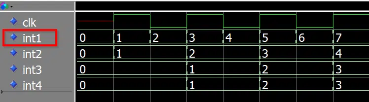
To be clear, let’s first look at an example using only a clk’event in an if-statement. The process below is sensitive to the clock signal, and within the if-statement, there is a single line of code that increments the int1 signal. This allows us to observe in the waveform when the program enters the if-statement.
process(clk)
begin

  if clk'event then
    int1 <= int1 + 1;
  end if;

end process;
The ‘event statement is what’s called an “attribute” in VHDL, a property that’s attached to a signal.
When we append ‘event to a signal name, it’s like calling a function. The ‘event attribute is like a built-in function in every signal, and when we call it, we get back a Boolean value: true or false. It returns true if there’s an event on the attached signal in that timestep (aka delta cycle) and false if there isn’t.
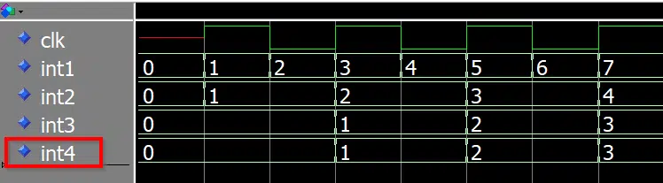
As we can see from the int1 signal in the waveform below, the if-statement triggers every time the clock changes. Not only when it changes from ‘0’ to ‘1’, and vice versa, but also when it goes from ‘U’ to ‘1’. That’s because ‘event returns true whenever the signal changes from something to something else.
Clk’event and clk = ‘1’
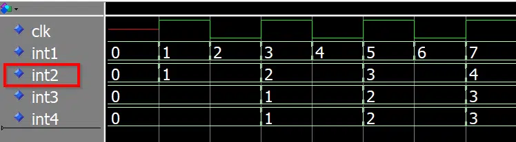
Now that we have a clear understanding of how ‘event works, we can look at the old-fashioned way of modeling the edge detector in VHDL. In the code below, we use clk’event in combination with a clk = ‘1’ to only trigger on transitions to ‘1’.
process(clk)
begin

  if clk'event and clk = '1' then
    int2 <= int2 + 1;
  end if;

end process;
As we can see from the waveform below, the int2 signal only increments when the clock changes to ‘1’. However, that includes the initial transition from ‘U’ to ‘1’. We can clearly see that int2 changes from 0 to 1 when clk changes from ‘U’, indicated by the red color line, to a green ‘1’ value.
This method works in implementation because there are no metavalues in the FPGA; there’s only ‘0’ and ‘1’. However, you may run into trouble in the simulation if you use clk’event carelessly.
I found an excellent example on StackOverflow that I will link to instead of stealing. Mr. Waugh argues that when simulating the I2C interface, it’s common to use the ‘H’ value to model the external pull-up resistor.
Because ‘H’ and ‘1’ have the same logic value, a transition from ‘H’ to ‘1’ wouldn’t trigger an edge detector in hardware. However, the two are not the same. So if you use clk'event and clk = '1' in this case, there will be a simulation mismatch.
It’s a legitimate way of creating an edge detector, but you have to be aware of the limitations.
Clk’event and clk’last_value = ‘0’ and clk = ‘1’
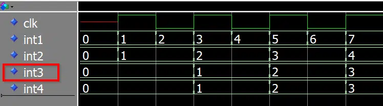
It is good to be explicit in VHDL. Give the synthesis tools less freedom, and you will be more happy. The same is true for testbenches; tell the simulator precisely what you want. In the example below, we include the ‘last_value attribute to ensure that only a transition from ‘0’ to ‘1’ triggers the if-statement.
process(clk)
begin

  if clk'event and clk'last_value = '0' and clk = '1' then
    int3 <= int3 + 1;
  end if;

end process;
We can see in the waveform below that it worked. The int3 signal only triggers when clk goes from ‘0’ to ‘1’. When the clock goes from ‘U’ to ‘1’ initially, nothing happens on int3.
Rising_edge()
Finally, let’s check out the rising_edge method of describing edge-sensitive logic. The code below shows the VHDL process, which triggers on a rising clock edge.
process(clk)
begin

  if rising_edge(clk) then
    int4 <= int4 + 1;
  end if;

end process;
As we can see from the waveform below, the rising_edge method (int4) behaves in the same way as our previous example (int3). That’s because they are logically equivalent.
The definition of the rising_edge function shown below is from the std_logic_1164 body in the GHDL project. It’s simply a convenience function that uses the most explicit edge detector statement to ensure that only a transition from ‘0’ to ‘1’ yields true.
function rising_edge (signal s : STD_ULOGIC) return BOOLEAN is
begin
  return (s'event and (To_X01(s) = '1') and
          (To_X01(s'last_value) = '0'));
end rising_edge;
Conclusion
While rising_edge(clk) and clk'event and clk = '1' are equivalent when implemented on the FPGA, the two statements may behave differently in simulation. The worst-case scenario of using the latter is that you may end up with a simulation that behaves differently from the implementation.
Leave your email in the form below to receive the complete VHDL code and ModelSim project!
Need the Questa/ModelSim project files?
Let me send you a Zip with everything you need to get started in 30 seconds
Tested on Windows and Linux Loading Gif..

Hi Jonas,
I’ve been following your posts for a while. All of them have been of great help for the preparation of my under-graduate classes in digital systems and VHDL. Thanks a lot!
Your simple but exquisite explanation of the differences between ‘event and rising_edge for signal edge detection, “forced” me to use this post in my class. I’d appreciate your understanding and permission 😉
Best regards!
Hello Roger,
Nice to hear from you, and thanks for the kind words!
My philosophy is that everything can be made simple if you break it down enough. ?
Regards,
Jonas
Hi Jonas,
Excellent value addition from your posts!! I have learnt so much on VHDL from you!!
Keep up the great work!!
Thanks!!
I’m happy to hear that. Thank you for the nice comment!
Hi Jonas,
i’ve followed your tutorials for a while. i was wondering if you would be interested in coming to Fermilab and provide a VHDL presentation/tutorial to our instrumentation group. we have several young and not so young engineers developing code and i think they would benefit from your expertise. Let me know if this a possibility and i can arrange with the lab about fees.
Thanks for your consideration
Peter Prieto
thank you so much
can we say :
CLK’EVENT AND CLK’LAST_VALUE = ‘0’ AND CLK = ‘1’
and rising_edge are the same !!!
Yes, we can! It’s easy. Isn’t it? 😊