Delta cycles are non-time-consuming timesteps used by VHDL simulators for modeling events during execution of VHDL code. They are events that happen in zero simulation time after a preceding event.
VHDL is a parallel programming language, while computers and CPUs work in a sequential manner. When a normal programming language is run, the CPU executes one instruction after the other. While in VHDL, there can be multiple sequences of logic that react to each other in ways that are not compatible with the standard computer architecture.
To precisely model the behavior of digital logic, simulators use an event-based approach for executing VHDL code.
Trivial example with no events
Let’s first look at what happens when we run this trivial VHDL code in the ModelSim VHDL simulator:
library ieee;
use ieee.std_logic_1164.all;

entity DeltaCyclesTb is
end entity;

architecture sim of DeltaCyclesTb is

    signal Sig1 : std_logic := '0';

begin

end architecture;
When I tell ModelSim to simulate this design for 200 hours, that works just fine, in fact, the simulation completes almost instantly, and the command prompt gives me a new line where I can enter the next command. How can it be that this very long simulation completed so fast?
VSIM 1> run 200 hr
VSIM 2>
You already know the answer intuitively. There is not a lot going on in this code. The Sig1 signal is '0' right from the start, and it doesn’t change at all. It is easy to know what the output will look like in a second or an hour from now, because it is exactly the same as now.
From the simulator’s point of view, there are no events in this VHDL code.
Event scheduling
This is the code from the previous example, but with an additional process that inverts the value of Sig1 every 5 nanoseconds:
library ieee;
use ieee.std_logic_1164.all;

entity DeltaCyclesTb is
end entity;

architecture sim of DeltaCyclesTb is

    signal Sig1 : std_logic := '0';

begin

    process is
    begin
        Sig1 <= not Sig1;
        wait for 5 ns;
    end process;

end architecture;
If we now try to simulate for 200 hours, it will take a lot of time. Instead, let’s run for 100 nanoseconds and have a look at the output in the waveform:
VSIM 1> run 100 ns
VSIM 2>
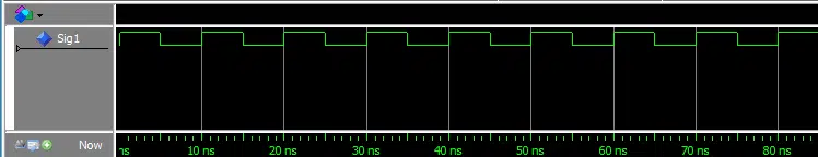
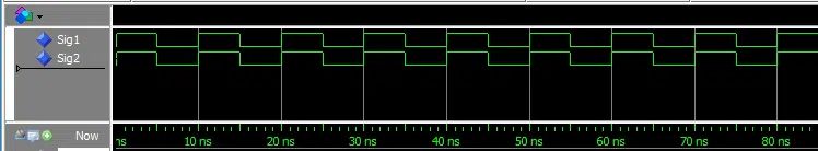
Unsurprisingly, Sig1 changes between '0' and '1' with a frequency of 100 MHz. Every time a signal changes, it is an event. But how does this work internally in the simulator?
Simulators use a technique called event scheduling to precisely model the behavior of VHDL code while doing the least amount of work.
At the start of the simulation, Sig1 has its initial value of '0'. Then, the simulator will run the process and stop at the wait for 5 ns; line. In VHDL, signal values are only updated when the process hits a Wait statement. In practice, the simulator will schedule the signal to have the new value in the next delta cycle.
The signal was '0' at the start of the simulation but changes to '1' before any time has passed at all. Although we are still at 0 ns simulation time, the signal now has a new value.
This is possible because a delta cycle is a zero-time timestep.
As the simulator executes the code, it will maintain an internal table of the next events that are scheduled to happen. For the above example, the event schedule will look like this:
| Simulation time | Sig1 current value | Sig1 scheduled value | Time to next event |
|---|---|---|---|
| 0 ns | ‘0’ | ‘1’ | 1 delta cycle |
| 0 ns + 1 delta cycle | ‘1’ | ‘1’ | 5 ns |
| 5 ns | ‘1’ | ‘0’ | 1 delta cycle |
| 5 ns + 1 delta cycle | ‘0’ | ‘0’ | 5 ns |
| The pattern repeats itself indefinitely | |||
Whenever a process is paused as the result of a Wait statement, the simulator keeps track of the future values of signals driven by that process and how long into the future it shall skip ahead before the next event is due to happen.
Show all delta cycles in the ModelSim waveform
By default, ModelSim will only log an object’s value at the start and at the end of a timestep. You will not be able to see beyond delta cycle +1 without changing the configuration file.
To make ModelSim show all delta cycles, “WLFCollapseMode = 0” must be set in the modelsim.ini file as shown below. The modelsim.ini file is located in the folder where you installed ModelSim.
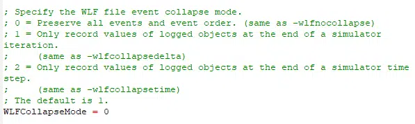
Remember to restart ModelSim after changing the ini file.
See how to install the free student edition of ModelSim here
Waveform with delta cycles expanded
In most simulators, it is possible to view delta cycle delays in the waveform. In ModelSim, you can do this by enabling “Expanded Time Deltas Mode”. Then, while placing the cursor on the transition you want to examine, press “Expand Time At Active Cursor”. After zooming in closely, delta cycle delays should be visible:
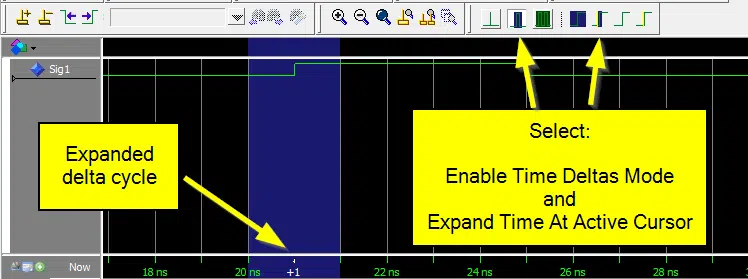
The above waveform shows delta cycles on the Sig1 signal from the previous code example.
Delta cycles as a result of sensitivity lists
We now know that a delta cycle delay will be produced if signal values have changed when the program hits a Wait statement. But what about processes with sensitivity lists?
In the code below, another process has been added to the testbench. The process which is sensitive to Sig1 will assign to Sig2 the value of Sig1 whenever Sig1 changes.
library ieee;
use ieee.std_logic_1164.all;

entity DeltaCyclesTb is
end entity;

architecture sim of DeltaCyclesTb is

    signal Sig1 : std_logic := '0';
    signal Sig2 : std_logic;

begin

    process is
    begin
        Sig1 <= not Sig1;
        wait for 5 ns;
    end process;

    process(Sig1) is
    begin
        Sig2 <= Sig1;
    end process;

end architecture;
The two signals appear to change simultaneously in the waveform, as one would expect:
When expanded to show delta cycles in the time period from 0 to 10 ns, the waveform looks like this:
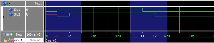
At 0 ns, none of the processes have run yet. Therefore, all signals will have their initial values. Sig1 has the value '0', which is the initial value we specified when the signal was declared. But Sig2 has the value 'U'. We didn’t explicitly give Sig2 an initial value. The 'U' value means “Uninitialized”. It is the default value of the std_logic type.
To understand what happens next, let’s take a step back and try to remember what a process with a sensitivity list really is. A process with a sensitivity list is equal to a process with a Wait On statement at the end. This is a well-defined part of the VHDL standard.
Using this information, we can rewrite process number two into:
process is
begin
    Sig2 <= Sig1;
    wait on Sig1;
end process;
When program execution starts, Sig2 will be scheduled to get the value of Sig1 in the next delta cycle. Then, the process will sleep until Sig1 changes. When that happens, the process will wake up, and the value will be copied once again.
The event schedule for the first 5 ns will look like this:
| Time + delta | Sig1 current / next | Sig2 current / next | Time to next event |
|---|---|---|---|
| 0 ns | ‘0’ → ‘1’ | ‘U’ → ‘0’ | 1 delta cycle |
| 0 ns +1 | ‘1’ | ‘0’ → ‘1’ | 1 delta cycle |
| 0 ns +2 | ‘1’ | ‘1’ | 5 ns |
| 5 ns | ‘1’ → ‘0’ | ‘1’ | 1 delta cycle |
| 5 ns +1 | ‘0’ | ‘1’ → ‘0’ | 1 delta cycle |
| 5 ns +2 | ‘0’ | ‘0’ | 5 ns |
The event schedule matches the waveform with expanded delta cycles. Take notice of the signal values in the last delta cycle in each of the timesteps. That is, when the “Time + delta” column reads “0 ns + 2” and “5 ns +2”.
Neither Sig1 nor Sig2 has a scheduled value at this point. That’s how the simulator knows that it is time to proceed to the next timestep, which is not a delta cycle. All changes have propagated through the logic, and there are no more scheduled changes.
There is no need for another delta cycle because all signals have stable values now. Nothing more can happen at this time. Another delta cycle would just result in the same values. The simulator jumps ahead to the next process that is due to wake up from a Wait For statement.
Simulator run time
Due to this scheduling scheme, simulator run time has no relation to the time values that are used in the simulated design. Waiting for 5 nanoseconds takes the same time as waiting for 5 hours. It’s just another value for the next timestep in the scheduling table.
The number of timesteps does affect the simulator run time. Every time the simulator has to stop and start, it adds to the run time. It makes the simulation slower because the simulator has to keep track of processes that wake up due to changing signal values, which may cause additional delta cycles.
The number of processes that are sensitive to the signals that are changing also affects the speed of the simulation. Usually, most of the logic will be sensitive to the clock signal. Therefore, lengthy simulations on clocked designs may take a substantial amount of time to simulate.
In the How to create a Timer tutorial, we avoided this problem by lowering the clock frequency in the testbench.
Course: Delta cycles in-depth
Understanding how delta cycles work in VHDL is key to becoming proficient in FPGA design. This course teaches you how signal scheduling works in simulation.
Creating delta cycles
Sometimes, you may want to create a delta cycle delay deliberately. In production (RTL) code, it is pointless, but in testbenches, it can be quite useful. Delta cycle pulses can be used to perform inter-process communication without consuming simulation time.
Testbenches often contain processes that act as bus functional models (BFMs). They provide the device under test (DUT) with stimuli and verify that its output is correct. Because testbenches don’t have to be synthesizable, we can use delta cycle pulses to our advantage.
It may sound counter-intuitive, but wait for 0 ns; is a perfectly valid VHDL statement.
As we already know, signal values are only updated when the process hits a wait statement. By waiting for a zero-time value, signals will get their scheduled values without any simulation time passing. The signals will get the new values in the next delta cycle but in zero simulation time.
Consider this code that creates two mirrored signal patterns:
library ieee;
use ieee.std_logic_1164.all;

entity DeltaCyclesTb is
end entity;

architecture sim of DeltaCyclesTb is

    signal Trigger : std_logic := '0';
    signal Sig1 : std_logic := '0';
    signal Sig2 : std_logic := '0';

begin

    process is
    begin
        wait for 100000 ns;

        -- Create a delta cycle pulse
        Trigger <= '1';
        wait for 0 ns;
        Trigger <= '0';

    end process;

    process is
    begin
        -- Wait for trigger pulse
        wait until Trigger = '1';

        for i in 1 to 50 loop
            Sig1 <= not Sig1;
            wait for i * 10 ns;
        end loop;

    end process;

    process is
    begin
        -- Wait for trigger pulse
        wait until Trigger = '1';

        for i in 1 to 50 loop
            Sig2 <= not Sig2;
            wait for (50 - i * 1) * 10 ns;
        end loop;

    end process;

end architecture;
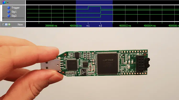
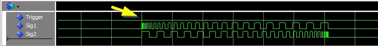
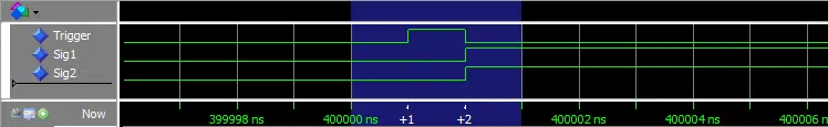
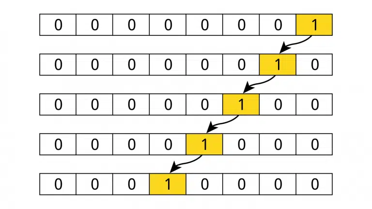
The above code results in the waveform that is shown below. The two signal patterns are mirrored but start and end at the exact same time. The Trigger signal is used for synchronously starting two processes that create each pattern.
The Trigger signal is pulsed within a delta cycle, shown by the yellow arrow in the waveform. Its value is '1' for the duration of zero time, but one delta cycle.
The same waveform is shown below, zoomed in on the trigger pulse, now with time deltas expanded in ModelSim. We can see from the timeline that Trigger is '1' between delta cycles +1 and +2.
This is an example of how you can use delta cycles to your advantage when creating testbenches, BFMs, and verification components.
Pitfalls
Signal value transitions that are seemingly in sync, but separated by delta cycles, can lead to bugs that are difficult to detect. The novice VHDL developer may even perceive delta cycles as a bug or imperfection in the VHDL language.
Delta cycles are neither bugs nor imperfections. They are an integral part of the scheme that enables us to design concurrent logic by using a programming language.
Even so, let’s go over two common problems that may arise due to delta cycle delays.
Copying the clock signal
A practice that will almost definitely lead to undesirable results is copying the clock signal. We have all done it at some point in our careers. You create a copy of the clock signal to give it a new name or for some other reason. Suddenly, all sorts of strange things happen when you run the simulation.
When you copy the clock signal, the copy will lag behind the original by one delta cycle. If different processes are using separate copies of the clock, they will no longer be in sync.
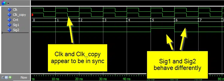
In the below code, the number of elapsed clock periods, Cnt, is counted by the one-liner process. The first process with a sensitivity list pulses Sig1 when the counter is 5. While the last process is an equivalent that pulses Sig2, but is sensitive to a copy of the clock.
library ieee;
use ieee.std_logic_1164.all;

entity DeltaCyclesTb is
end entity;

architecture sim of DeltaCyclesTb is

    signal Clk : std_logic := '1';
    signal Clk_copy : std_logic;
    signal Cnt : integer := 0;
    signal Sig1 : std_logic := '0';
    signal Sig2 : std_logic := '0';

begin

    Clk <= not Clk after 5 ns;
    Cnt <= Cnt + 1 when rising_edge(Clk);
    Clk_copy <= Clk;

    -- Pulse after 5 clock cycles
    process(Clk) is
    begin
        if rising_edge(Clk) then
            Sig1 <= '0';
            if Cnt = 5 then
                Sig1 <= '1';
            end if;
        end if;
    end process;

    -- Equivalent process, but using Clk_Copy
    process(Clk_copy) is
    begin
        if rising_edge(Clk_copy) then
            Sig2 <= '0';
            if Cnt = 5 then
                Sig2 <= '1';
            end if;
        end if;
    end process;

end architecture;
In the waveform below, the two clocks appear to be in sync. But still, the identical processes behave differently. The process that uses a copy of the clock reacts one clock cycle before the one that is using the original.
The below image shows the same waveform, but with time deltas expanded around the transition of the counter from 4 to 5. Here, it’s possible to spot the reason for the error. The copied clock is delayed by one delta cycle.
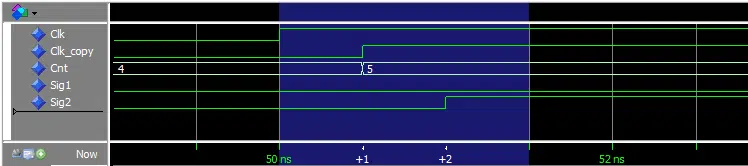
At the rising edge of the original clock, the process that is sensitive to it wakes up and samples Cnt, which is 4. The process that increments Cnt is also sensitive to the original clock. It too wakes up in the same delta cycle and schedules a change to the Cnt signal.
The change is effective in the next delta cycle. Meanwhile, the process using a copy of the clock has been delayed by one delta cycle because of the delta cycle delay on the copied clock. When it wakes up, the Cnt signal has changed and is now 5. It will sample the new counter value. Therefore, it will behave differently from the process using the original clock.
Simulation mismatch due to delta cycle delay
Now you know that copying the clock is bad because it can lead to the simulation not working properly. But what happens if we try to synthesize code that contains copied clock signals?
I implemented a LED blink module on the Lattice iCEstick development board. It contains two identical counter processes and a process for toggling the LED. But one of the counter processes are using a copied clock. If the two counters are synchronous, the LED will blink periodically.
Watch the video to find out how it went!
The testbench which instantiates the module:
library ieee;
use ieee.std_logic_1164.all;

entity DeltaCyclesTb is
end entity;

architecture sim of DeltaCyclesTb is

    signal Clk : std_logic := '1';
    signal Led1 : std_logic;

begin

    Clk <= not Clk after 41.66 ns; -- 12 MHz

    i_DeltaCycles : entity work.DeltaCycles(rtl) port map (
        Clk => Clk,
        Led1 => Led1
    );

end architecture;
The LED blink module that is instantiated in the testbench and which is running on the Lattice iCEstick:
library ieee;
use ieee.std_logic_1164.all;
use ieee.numeric_std.all;

entity DeltaCycles is
port (
    Clk : in std_logic;
    Led1 : out std_logic
    );
end entity;

architecture rtl of DeltaCycles is

    signal Clk_copy : std_logic;
    signal Cnt1 : unsigned(23 downto 0) := (others => '0');
    signal Cnt2 : unsigned(23 downto 0) := (others => '0');
    signal Led1_i : std_logic := '0';

begin

    Led1 <= Led1_i;

    Clk_copy <= Clk;

    Cnt1 <= Cnt1 + 1 when rising_edge(Clk);
    Cnt2 <= Cnt2 + 1 when rising_edge(Clk_copy);

    process(Clk_copy) is
    begin
        if rising_edge(Clk_copy) then
            if Cnt1 = 0 and Cnt2 = 0 then
                Led1_i <= not Led1_i;
            end if;
        end if;
    end process;

end architecture;
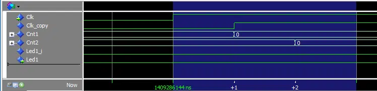
The waveform with expanded time deltas show how the delta cycle delay on the clock prevents the toggle process from sampling the counters when they are equal:
But why did the module work when implemented on an FPGA board?
The synthesizer ignored the copied clock signal and treated the two clocks with different names as one single net. The synthesizer’s job is to create a netlist from the code that can be implemented with the available physical resources. Now, how should a zero-time delay on the same wire be implemented?
Think about that.
With the line Clk_copy <= Clk; we are saying; whenever Clk changes, transfer that value to Clk_copy in zero time. The synthesizer is doing the only thing it can do. By joining the two signals to create a single net, the value will be transferred as fast as possible.
Gate-level simulation
What about the simulation, is there a bug in ModelSim? No, there is no bug.
What we are experiencing is a consequence of simulating a digital electronic circuit using a higher-level programming language. ModelSim does not have any knowledge of the technology we are going to implement the code on. It simulates the VHDL code, which is at a higher abstraction level than the logic gates and flip-flops are.
There are options in ModelSim and other VHDL simulators to perform gate-level simulation. This is a process where the implemented netlist is fed back into the simulator from the synthesizer. If we had done a gate-level simulation on the design, we would have seen the same behavior as we did in real life.
Course: Delta cycles in-depth
Understanding how delta cycles work in VHDL is key to becoming proficient in FPGA design. This course teaches you how signal scheduling works in simulation.
Are delta cycles evil?
You should know by now that delta cycles are not evil. There is nothing mystical or magical about them. They are, in fact, what makes it possible for us to simulate VHDL with predictable, repeatable results.
However, when coding with VHDL, you need to be aware of the differences between simulation and synthesis. You need to keep a mental event schedule that you invoke when you create a new process or update a signal.
Master the delta cycle, and you will for sure become a better VHDL engineer.

Brilliant write up, I’ve been working with FPGA for more than 15 years. Still once in a while need to refresh these fundamentals.
This is the best blog I found about Delta Delay by Google.
Thanks! That’s a nice thing to hear from someone with more experience than me. I always try to go for quality over quantity when writing my blog posts.
Agreed, it’s an excellent description of a very fundamental concept of understanding VHDL. As Ethan says it’s always a good idea to have a refresh of the basics every once in a while.
If only there were an equally good article (with an example) on the verilog stratified event queue.
Great article, this clears up a lot of things I did not understand fully.
This is undoubtedly the best description of VHDL
I’m really glad to read this before more coding
Thanks a lot!
Thanks, Arman, I’m glad you found this blog post to be helpful.
VHDL is NOT a parallel programming language, it is a hardware description language.
There is a huge difference between understanding of parallel programming language and hardware description language.
Hello Akbar,
There’s an age-old discussion about if you can refer to VHDL as a programming language or not.
I do agree with you that learning VHDL requires a different understanding than learning a computer programming language. And it’s a hardware description language, no doubt about it; it’s in the name.
But is it a programming language?
When I’m writing a VHDL module, one that goes on the FPGA, I am thinking in terms of hardware. If I need a multiplexer, I write a VHDL process that describes the behavior of it, and so on.
But when I’m creating testbenches, I don’t think about hardware at all. I use it more like a programming language. Within each process, the program executes sequentially, and all of the processes run in parallel, like well-coordinated threads. The testbench doesn’t describe hardware. It runs in the simulator, like a parallel programming language.
I guess the terminology can be debated, but for some people, it helps to think about VHDL as a parallel programming language. At least I’m not the only one who does this, the Wikipedia page for VHDL also uses the term.
Hi Jonas, congrats as always for such an excellent post!
I was probing different things with your code and I wondered why the statement (Clk <= not Clk after 5 ns) do not add a delta cycle.
In the past I used to generate the CLK signal inside a process, but I wasn't aware doing that way generates a delta cycle in the clk signal.
Hello Dante,
It’s OK to generate the clock in a process, even though it adds a delta cycle delay. As long as you don’t copy the clock, the delta delay doesn’t matter since all instances are seeing the same delay.
But it’s an interesting point that you are raising, which I didn’t answer in this article. Why is the clock generated using
Clk <= not Clk after 5 ns;changing right on the 5 ns marks, while the clock generated in a process doesn't?Let's create a little experiment to understand better why this happens. The code below shows four different ways to generate a 100 MHz clock.
  signal clk1, clk2, clk3, clk4 : std_logic := '1';

begin

  clk1 <= not clk1 after 5 ns;

  process
  begin
    clk2 <= not clk2 after 5 ns;
    wait for 5 ns;
  end process;

  process
  begin
    clk3 <= not clk3 after 0 ns;
    wait for 5 ns;
  end process;

  process
  begin
    clk4 <= not clk4;
    wait for 5 ns;
  end process;
The
clk1signal is controlled by a concurrent process that uses theafterkeyword.According to the VHDL standard, the
afterkeyword specifies "that the driver is to assign a particular value to the target at the specified time". Thus, there's no reason to have a delta cycle delay before the changing value. The signal is scheduled to change every 5 ns, and that's all there is to it.https://vhdlwhiz.com/wp-content/uploads/2021/01/clock-delta-cycles.png
Now, watch what happens in the waveform above when we put that in a process to generate
clk2.It is also in sync with the zero-delta time value, even though the second process does a
wait for 5 ns;. That's because every time the process is waking up, we are scheduling a change 5 ns into the future. It's 5 ns simulation time into the future, not 5 ns + 1 delta cycle, and that's what we are getting.Finally, the two last processes are equivalent because according to the VHDL standard: "If the after clause of a waveform element is not present, then an implicit “after 0 ns” is assumed."
Here we see the +1 delta cycle delay on
clk3andclk4. It happens because when the process wakes up every 5 ns, the next line schedules a new value onto the signals after 0 ns. And because we are already at the simulation time when the change should occur, it must happen in the next delta cycle (+1).Thanks for asking an interesting question! I had fun with it. ?
Jonas,
thanks for taking your time and give such a meaningful answer. Maybe this reply is not necessary, but I didn’t want to not saying thanks to you. Delete it if you consider necessary.
This is an excellent resource, thank you. I’ve been working as a professional FPGA developer for several years now and learning some good new fundamentals that I probably should have learned before!
Thanks for the nice comment, Jon. It means a lot to me, and especially when coming from an experienced FPGA engineer. 🙂
What a brilliant blog article! I just recently finished my Masters Degree and started working as a FPGA Engineer and these concepts are still new to me. These Articles help me understand advanced concepts so much better. Thank you so much for the time and effort invested in this. I really hope you can keep it up!
Greetz from Berlin
Thank you for the nice comment! I’m glad you found it helpful. 🙂
Thank you for this excellent reference to point people to.
> What about the simulation, is there a bug in ModelSim? No, there is no bug.
I’m struggling with this “no” having fallen foul of the issue of copied clocks a few times (obviously in other people’s code … ahem). My issue is that simulation does not mirror real life, as you eloquently explained about synthesis. If a copied clock works in synthesis, then it should simulate as expected, with no delta cycle. This is probably one of those “horse has bolted now” scenarios. I propose what should have been done many years ago, was to treat an assignment with no logic as if it were a VHDL ‘alias’. then there is no delta cycle. The compiler should be able to discern there is no logic on the right hand side of the assignment and hence no delta cycle for the purposes of correct simulation. I guess its too late now because if you change the behaviour of the simulator, old code that is relied upon starts to fail.
Fundamentally the difference between real life and simulation is a problem.
This also happens in Vivado IP where some components they offer assign an output clock from an input clock. Don’t be fooled into blindly using the IP’s copied clock output (don’t forget you can’t see inside the IP protected code), as it will have a delta cycle and the original clock on the IP’s input should be used instead.
Delta cycles are not evil, but essential for logic simulation but I still feel they have been used inappropriately in the case of a “wire” connection. If multiple names for a clock are required, use an ‘alias’.