A self-checking testbench is a VHDL program that verifies the correctness of the device under test (DUT) without relying on an operator to manually inspect the output. The self-checking testbench runs entirely on its own, and prints an “OK” or “Failed” message in the end.
Every VHDL module should have an associated self-checking testbench. It’s important to be able to verify that all modules have the intended behavior at any time. For example, when you make changes to the DUT, a sub-module, or an interfacing module. We all know that stuff can break, and your best tool for catching these problems is the self-checking testbench.
The device under test
Let’s jump right in and create an example of a self-checking testbench. First, we need something to test, a DUT. For that I have created the module in the code below. It’s a binary to Gray code converter.
library ieee;
use ieee.std_logic_1164.all;

entity gray_converter is
  port (
    bin : in std_logic_vector;
    gray : out std_logic_vector
  );
end gray_converter;

architecture rtl of gray_converter is
begin

  process(bin) is
  begin
    gray(gray'high) <= bin(bin'high);

    for i in bin'high - 1 downto bin'low loop
      gray(i) <= bin(i + 1) xor bin(i);
    end loop;

  end process;

end architecture;
Gray code is an alternative number coding scheme, different from regular binary encoding. The main property and purpose of Gray code is that only one bit changes when counting between adjacent number values.
| Decimal | Binary | Gray |
|---|---|---|
| 0 | 0000 | 0000 |
| 1 | 0001 | 0001 |
| 2 | 0010 | 0011 |
| 3 | 0011 | 0010 |
| 4 | 0100 | 0110 |
| 5 | 0101 | 0111 |
| 6 | 0110 | 0101 |
| 7 | 0111 | 0100 |
| 8 | 1000 | 1100 |
| 9 | 1001 | 1101 |
| 10 | 1010 | 1111 |
| 11 | 1011 | 1110 |
| 12 | 1100 | 1010 |
| 13 | 1101 | 1011 |
| 14 | 1110 | 1001 |
| 15 | 1111 | 1000 |
The table above shows how Gray code differs from binary code.
The testbench
We shall start by creating the basic testbench and instantiating the DUT within it. The code below shows the testbench file with the DUT instantiated and all the necessary imports.
library ieee;
use ieee.std_logic_1164.all;
use ieee.numeric_std.all;

use std.env.finish;

entity gray_converter_tb is
end gray_converter_tb;

architecture sim of gray_converter_tb is

  signal bin : std_logic_vector(3 downto 0) := (others => '0');
  signal gray : std_logic_vector(3 downto 0);

begin

  DUT : entity work.gray_converter(rtl)
  port map (
    bin => bin,
    gray => gray
  );

end architecture;
Note that we are importing std.env.finish which requires VHDL-2008. If you try to compile the testbench in ModelSim without changing anything, you will get the following error:
# ** Warning: gray_converter_tb.vhd(6): (vcom-1516)
Package "STD.ENV" does not exist in this language version.
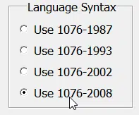
Fortunately, this can easily be fixed by setting the VHDL version for the testbench file to VHDL-2008. Right-click the testbench .vhd file and select Properties→VHDL→Use 1076-2008->OK.
You don’t need to change anything for the DUT. It’s normal to use a higher version of VHDL for testbenches than for the RTL modules. You always want to be able to use the latest VHDL constructs in your testbench, but most synthesis tools don’t support them.
Generating the input
Our next addition to the testbench will be the process that generates inputs for the DUT. It’s always best to create an exhaustive test, a test that tries all possible input values. Although, if there are too many permutations, you may be restricted to doing only corner cases.
The input and outputs of our DUT is of unspecified range. However, I will make an educated guess that testing with vector lengths of four bits is enough to reveal any possible issue with this module.
The code below contains the entire process for generating the input sequence.
PROC_SEQUENCE : process
begin

  -- Test all possible input values
  for i in 0 to 2**bin'length - 1 loop
    bin <= std_logic_vector(to_unsigned(i, bin'length));
    wait for 10 ns;
  end loop;

  -- Finally, test the wrapped value
  bin <= (others => '0');
  wait for 10 ns;

  report "Test: OK";
  finish;

end process;
The first code chunk is a For loop which generates the counting sequence from the lowest possible value to the highest possible value. In between the values, we wait for 10 nanoseconds to allow the DUT to react. Although, any nanosecond value greater than 0 would have worked, because the logic inside of the DUT is purely combinational.
The second chunk of code is for testing the situation where the input counter goes back to 0, which was the initial input value. After that, there is no need for further testing because the DUT will just continue to yield the same results over and over again.
The final two code lines within the process is for ending the test gracefully. The text “Test: OK” is printed to the console, and then the simulation is stopped by using the VHDL-2008 keyword “finish”.
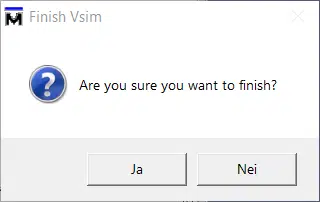
Note that if you run ModelSim with the default Run-button, ModelSim will prompt you with the quit dialog after the testbench completes successfully. This behavior may be changed when launching Vsim from a script or from the command line. Add the “-onfinish stop” switch to the Vsim command, as described in the ModelSim command reference.
Checking the output
Now we are supplying the DUT with inputs, but there is no checking of the output at all. The testbench will print out “Test: OK”, regardless if the output is correct or not. Let’s do something about that.
When creating a verification algorithm, you should always try to implement the test differently than in the DUT. Otherwise, a fundamental flaw in the logic may go unnoticed because it’s present in the DUT as well as in the testbench algorithm.
Following this principle, we are going to test the DUT output not by checking that the Gray code is correct, but rather that only one bit changes from one number to the next. After all, that’s the whole reason for using Gray code in the first place. The code below shows a process that performs this kind of checking.
PROC_CHECKER : process
    variable prev : std_logic_vector(gray'range);
    variable count : integer;
begin
  wait on bin;

  prev := gray;

  -- Wait for all delta cycles to propagate
  wait for 1 ns;

  -- Count the number of changed bits
  count := 0;
  for i in gray'range loop
    if gray(i) /= prev(i) then
      count := count + 1;
    end if;
  end loop;

  assert count = 1
    report integer'image(count) & " bits changed, should have been 1"
    severity failure;

end process;
The process is sensitive to the bin signal, the input to the DUT. We could have used a sensitivity list with the same result, but I prefer to use only Wait statements in testbench code. It’s a convention that makes it easy to know if you’re dealing with a testbench or an RTL module just by looking at how the code is written.
On the seconds line, we copy the previous DUT output. Remember, this is the first delta-cycle after the bin signal has changed, and the DUT cannot possibly react yet. So, it is safe to copy the DUT output with the assumption that this is the old value.
Then, we wait for 1 nanosecond to allow all combinational logic in the DUT to complete. Now, the DUT output should be stable, and we can safely examine its value.
In the next chunk of code, we use a For loop for counting the number of changed bits on the DUT output.
Finally, comes the Assert statement that checks that the number of changed bits is exactly 1. Assert statements work by checking the condition, which is this case is count = 1. If the condition evaluates to false, an assertion will be raised, and the simulator will stop before the “Test: OK” message is printed out.
It’s wise to include the optional report statement with the assert statement. This text will be printed out if the assertion fails. In our example, I provide a brief explanation of the event that caused the testbench to fail.
Running the testbench
It’s time to run our testbench to verify that the DUT is working correctly. After starting the simulation in ModelSim, and pressing the “run -all” button, we see that the “Test: OK” message is printed to the console.
VSIM 1> run -all
# ** Note: Test: OK
#    Time: 170 ns  Iteration: 0  Instance: /gray_converter_tb
Need the Questa/ModelSim project files?
Let me send you a Zip with everything you need to get started in 30 seconds
Tested on Windows and Linux Loading Gif.. 
Testing the testbench
I always like to create a failing condition in the DUT just to see that the testbench works. Sometimes this comes naturally due to actual errors in the DUT while you are developing it. But if it doesn’t, just create an error briefly to test the testbench.
To achieve this, I will edit the DUT code to create a stuck at 0 error on bit number 3. After this test, I will remove the error with the knowledge that the testbench is able to detect such errors. The code below shows the DUT process with the additional code line.
process(bin) is
begin
  gray(gray'high) <= bin(bin'high);

  for i in bin'high - 1 downto bin'low loop
    gray(i) <= bin(i + 1) xor bin(i);
  end loop;

  -- Emulate a stuck at zero error
  gray(3) <= '0';

end process;
When we run the testbench now, we can see that the testbench stops, and the error is printed out before the “Test: OK” line is reached. The transcript from the ModelSim console is shown below.
VSIM 2> run -all
# ** Failure: 0 bits changed, should have been 1
#    Time: 81 ns  Iteration: 0
Process: /gray_converter_tb/PROC_CHECKER File: gray_converter_tb.vhd
# Break in Process PROC_CHECKER at ray_converter_tb.vhd line 61
Getting started with self-checking testbenches
You should be able to create a self-checking testbench by using what you have learned in this article. Make it a habit to always create self-checking testbenches for all of your VHDL modules. It will save you time in the long run.
It’s OK to be creative when writing testbenches. More so than when writing RTL modules because not all VHDL constructs can be synthesized, but the testbench doesn’t need to be synthesizable. Expect to spend at least as much time writing tests as you spend on writing the DUT.
If you want to get serious about testing, you may be interested in my *upcoming VHDL and FPGA course. In the course, I will walk you through the complete design process from idea to the physical working FPGA prototype. We will create multiple self-checking testbenches.
Updated 12th of October 2020: I have completed the course. Click the image below to learn more.
I will teach you the best practices for successfully creating VHDL and FPGA designs the right way. Knowledge that I have acquired through many years in academia and after working as a hardware engineer in the defense industry will be passed on to you.


variable prev : std_logic_vector(gray’range); can you exaplain about these keywords
variable
A variable in VHDL behaves as variables do in other programming languages, but it’s different from a signal. Check out my tutorial to learn more about that:
How a Signal is different from a Variable in VHDL
The
std_logic_vectorpart is an array of bits in VHDL. Learn about it here:How to create a signal vector in VHDL: std_logic_vector
And finally,
'rangeis what’s called an attribute in VHDL. It’s like a subprogram or value that’s attached to a signal.gray'rangereturns the range that thegraysignal was declared to have:(3 downto 0).