In the previous tutorial we used a conditional expression with the Wait Until statement. The expression ensured that the process was only triggered when the two counter signals where equal. But what if we wanted the program in a process to take different actions based on different inputs?
The If-Then-Elsif-Else statements can be used to create branches in our program. Depending on the value of a variable, or the outcome of an expression, the program can take different paths.
This blog post is part of the Basic VHDL Tutorials series.
The basic syntax is:
if <condition> then
elsif <condition> then
else
end if;
The elsif and else are optional, and elsif may be used multiple times. The <condition> can be a boolean true or false, or it can be an expression which evaluates to true or false.
Example expression which is true if MyCounter is less than 10:
MyCounter < 10
Relational operators:
| = | equal |
| /= | not equal |
| < | less than |
| <= | less than or equal |
| > | greater than |
| >= | greater than or equal |
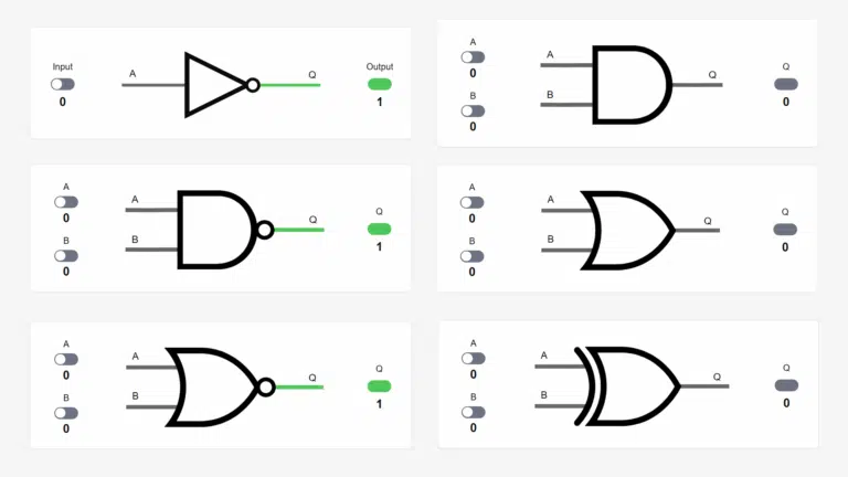
Logical operators:
| not a | true if a is false |
| a and b | true if a and b are true |
| a or b | true if a or b are true |
| a nand b | true if a or b is false |
| a nor b | true if a and b are false |
| a xor b | true if exactly one of a or b are true |
| a xnor b | true if a and b are equal |
Exercise
In this video tutorial we will learn how to use If-Then-Elsif-Else statements in VHDL:
The final code we created in this tutorial:
entity T08_IfTb is
end entity;

architecture sim of T08_IfTb is

    signal CountUp   : integer := 0;
    signal CountDown : integer := 10;

begin

    process is
    begin

        CountUp   <= CountUp + 1;
        CountDown <= CountDown - 1;
        wait for 10 ns;

    end process;

    process is
    begin

        if CountUp > CountDown then
            report "CountUp is larger";
        elsif CountUp < CountDown then
            report "CountDown is larger";
        else
            report "They are equal";
        end if;

        wait on CountUp, CountDown;

    end process;

end architecture;
The output to the simulator console when we pressed the run button in ModelSim:
VSIM 2> run
# ** Note: CountDown is larger
#    Time: 0 ns  Iteration: 0  Instance: /t08_iftb
# ** Note: CountDown is larger
#    Time: 0 ns  Iteration: 1  Instance: /t08_iftb
# ** Note: CountDown is larger
#    Time: 10 ns  Iteration: 1  Instance: /t08_iftb
# ** Note: CountDown is larger
#    Time: 20 ns  Iteration: 1  Instance: /t08_iftb
# ** Note: CountDown is larger
#    Time: 30 ns  Iteration: 1  Instance: /t08_iftb
# ** Note: They are equal
#    Time: 40 ns  Iteration: 1  Instance: /t08_iftb
# ** Note: Countup is larger
#    Time: 50 ns  Iteration: 1  Instance: /t08_iftb
# ** Note: Countup is larger
#    Time: 60 ns  Iteration: 1  Instance: /t08_iftb
...
Analysis
We gave CountDown an initial value of 10, and CountUp a value of 0. The first process changes both counter values at the exact same time, every 10 ns. When this happens, the second process is triggered because the program will always be waiting at the wait on CountUp, CountDown; line. The program will always be waiting there because the If-Then-Elsif-Else and the report statements consume zero simulation time.
The If-Then-Elsif-Else statement will cause the program to take one of the three branches we created. The two first branches cover the cases where the two counters have different values. We could have dropped the single else, and used elsif CountUp = CountDown then which would have had the same result. But it is good design practice to cover all branches, and the else clause covers all intentional and unforeseen cases.
As we can see from the printout, the second process takes one of the three branches every time the counters change.
Get free access to the Basic VHDL Course
Download the course material and get started.
You will receive a Zip with exercises for the 23 video lessons as VHDL files where you fill in the blanks, code answers, and a link to the course.
By submitting, you consent to receive marketing emails from VHDLwhiz (unsubscribe anytime).
Takeaway
- If-Then may be used alone or in combination with Elsif and Else.
- Expressions may contain relational and logical comparisons and mathematical calculations.


I have a small question:
Why the output is different if the line “wait on CountUp, CountDown;” is changed at the beginning of the process instead of the end?
The values of the signals are the same but in the firsts 0 ps make two times the operations. It concerns me in the sense of how the second process affect the time of operations even when the operations is not inside this process.
Hello, Tonatiuh. That’s a great observation!
It behaves like that because of how processes and signals work in the simulator.
When the simulation starts, all processes run simultaneously, and they pause at the first Wait statement. This happens in the first timestep (called “delta cycle” in the VHDL world).
Also, signal values become effective only when the process hits a Wait statement. Because of this, the two signals will retain their initial values during delta cycle 0.
Then, at delta cycle 1, both processes are paused at their Wait statements. But this is also the delta cycle when the initial change on CountUp/CountDown happens, which causes the second process to wake up once again.
Finally, after delta cycle 1, there are no more events until 10 ns later.
All of this happens in zero time, and it’s unnoticeable in the regular waveform view. But if we tell ModelSim to show delta cycles, as shown in the image below, we can spot the events at the beginning of the timeline.
https://vhdlwhiz.com/wp-content/uploads/2020/12/countup-countdown-deltas.png
The behavior of processes and signals is very predictable, and understanding this mechanism is key to becoming successful in VHDL design. I recommend my in-depth article about delta cycles:
Delta cycles explained
Thank you very much!!
Hi
I am trying to write a program to give me an out put (Z) of 1 if from 3 inputs(A,B & C), two are 1 and one is 0. I wrote the below statement but the error message said “error near if “. Please advise.
Thanks,
Mehdi
if (A and B =1 and C=0) then Z<=1
Hello, Mehdi. You can put the IF-ELSE in a process like this:
process(A, B, C)
begin

  if A = '1' and B = '1' and C = '0' then
    Z <= '1';
  else
    Z <= '0'; -- (Or something else)
  end if;

end process;
Or use the one-liner WHEN-ELSE notation outside of a process. This is equivalent to the process above:
Just a quick question, what would be the best approach to create an if statement based on the condition of an LED on a FPGA , for example if the LED0 was high then it would trigger a case ?
Create a combinational process like this:
process(my_led_signal)
begin
  if my_led_signal = '1' then
    -- Do something
  else
    -- Do something else
  end if;
end process;
However, it may be that what you want to happen when the LED is on is more complicated than simply setting some other signals.
In that case, you should look into clocked processes and state machines.
There is something wrong with your web page. In Firefox, much of the text is muted to a light grey which does not present well on a white background. It is nearly unreadable.
I’m sure this is some sort of coding error in the HTML as no one would choose such colors if they wanted people to be able to read their web pages.
I’m posting here, because I didn’t see another way to contact you.
I’ve updated the VHDLwhiz site today and the comments should be easier to read. Thanks for letting me know!