Have you ever wanted to run a VHDL simulation that includes a Quartus IP core through the VUnit verification framework?
That’s what FPGA engineer Konstantinos Paraskevopoulos had in mind, but he couldn’t find a suitable tutorial for it. Fortunately, he used his talent to figure out how and was kind enough to share it with VHDLwhiz through this guest article.
Now, let’s give the word to Konstantinos!
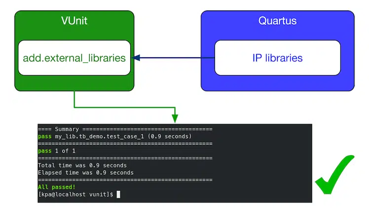
It is often desirable to incorporate predefined IPs from the Quartus IP Catalog into your design when simulating your system with VUnit. Thus, the following tutorial aims to supply the reader with knowledge of generating, incorporating, and linking external Quartus IP libraries to the VUnit environment.
New to VUnit? Check out this tutorial: Getting started with VUnit
Overview
This tutorial consists of three main parts :
- A brief description of the selected IP
- Steps required to generate and link the appropriate libraries
- Verification by utilizing VUnit and Modelsim
Requirements
- Quartus
- Download Quartus Prime
- QSYS should be in your PATH for STEP 2 (CMD option)
- Intel Modelsim
- Please refer to this article for how to install ModelSim for free
- ModelSim should be in your PATH
- VUnit
- Please refer to this article for how to install VUnit for free
- Python 3.6 or higher
- Download Python
- Python should be in your path
It also assumes having basic VHDL knowledge and ModelSim skills.
Design under test
For our scenario, we utilize the Parallel Adder IP from the Quartus Integer Arithmetic IP list.
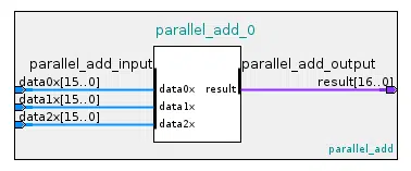
Our design accepts three 16-bit input vectors and outputs the added result in a 17-bit vector.
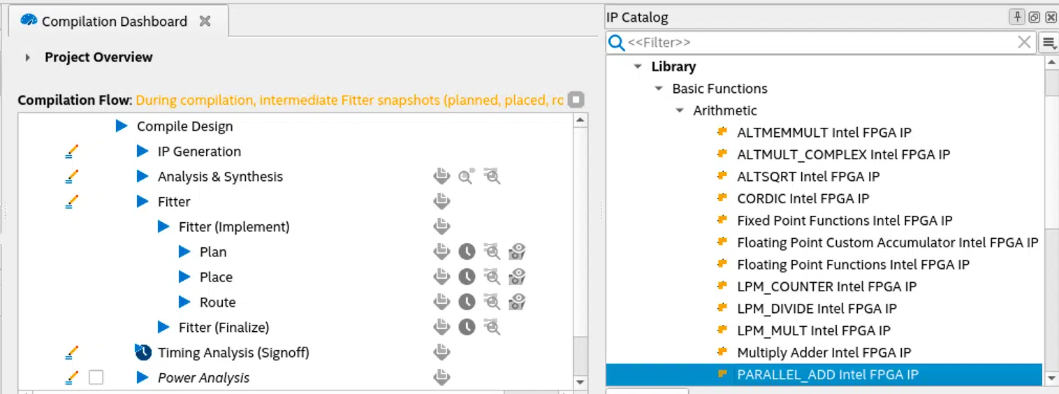
Step 1 : Generate IP
We generate our adder at the IP catalog window by double-clicking the parallel adder component under Library/Basic functions/Arithmetic.
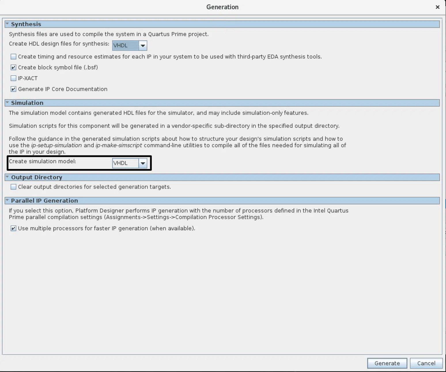
After we provide a name and customize our component based on our needs, we click the Generate HDL button at the bottom-right.
At this point, a window will appear, as depicted in the following figure.
Note: We must set the Create simulation model under the Simulation section to either VHDL or Verilog to generate the simulation files since the default option is none. If we don’t choose one, the given_ip_name.spd file will not be generated, causing the next step to fail.
The above process generates a file and a folder under our quartus directory:
- File:
given_ip_name.ip - Folder:
given_ip_name
The folder entails .vhd and .v files that need to be added later in our run.py script.
Step 2 : Generate IP simulation files
- GUI: Select Tools ➤ Generate Simulator Setup Script for IP and specify output directory in the prompt window,
- CMD: By utilizing Qsys commands, we can generate the same files by typing in the terminal the following command:
ip-setup-simulation --quartus-project= <project's_QPF_filepath>
--output-directory= <my_dir>
Using one of the two methods above, we instruct Quartus to generate a directory for each supported simulator that holds a script to create and compile the IP libraries.
Step 3: Generate and compile IP libraries for Modelsim
The next step is to find the msim_setup.tcl script in the mentor folder created by the previous step and duplicate it with the name setup.tcl. Then, in the setup.tcl file, uncomment the illustrated commands and set the $QSYS_SIMDIR variable.
# # QSYS_SIMDIR is used in the Quartus-generated IP simulation script to
# # construct paths to the files required to simulate the IP in your Quartus
# # project. By default, the IP script assumes that you are launching the
# # simulator from the IP script location. If launching from another
# # location, set QSYS_SIMDIR to the output directory you specified when you
# # generated the IP script, relative to the directory from which you launch
# # the simulator.
# #
 set QSYS_SIMDIR <script generation output directory>;
# #
# # Source the generated IP simulation script.
 source $QSYS_SIMDIR/mentor/msim_setup.tcl
# #
# # Set any compilation options you require (this is unusual).
# set USER_DEFINED_COMPILE_OPTIONS <compilation options>
# set USER_DEFINED_VHDL_COMPILE_OPTIONS <compilation options for VHDL>
# set USER_DEFINED_VERILOG_COMPILE_OPTIONS <compilation options for Verilog>
# #
# # Call command to compile the Quartus EDA simulation library.
 dev_com
# #
# # Call command to compile the Quartus-generated IP simulation files.
 com
# #
After altering and saving the setup.tcl, we can safely execute the Tcl file using the vsim command.
vsim -c -do "do setup.tcl; quit"
That generates the compiled libraries in the mentor folder.
Step 4: VUnit link
Now that the IP libraries have been generated, we should link them by using the python run.py script.
Check out the figure below to better understand our example’s directory structure. The initial topology consisted of the root folder demo, the tb, vunit, and quartus folders. All subfolders and files under the quartus folder are generated via the Quartus framework after creating a project and completing steps 1 to 3.
Note: Quartus generates more files and folders, but the image below shows those of interest to us.
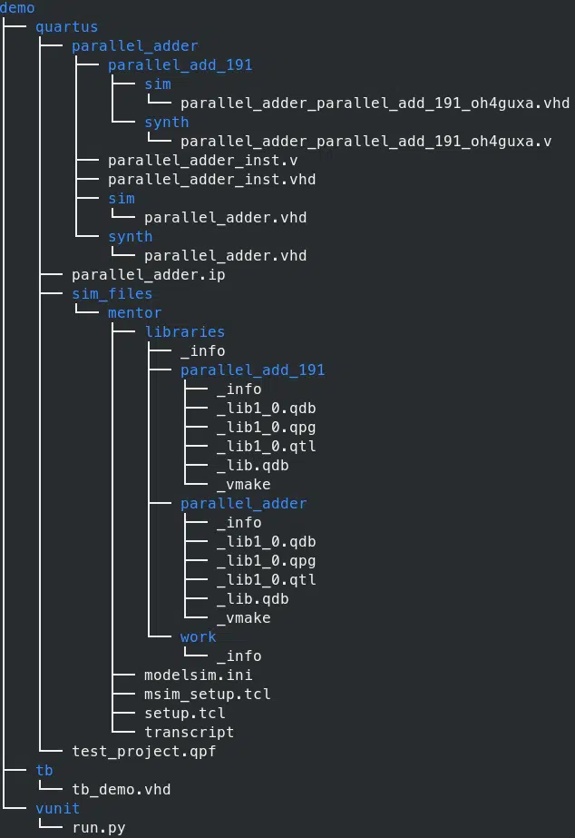
Using this distinct view of the topology as a reference, we can specify our ROOT path and the path(s) to the generated libraries, as shown below.
Note that sim_files is the directory we specified in step 2 where the mentor folder has been stored.
from vunit import VUnit
from os.path import join, dirname, abspath
# ROOT
root = join(dirname(__file__), '../')
# Path to generated libraries
path_2_lib = '/quartus/sim_files/mentor/libraries/'
# ROOT
After creating a VUnit instance called vu, we can specify a design library for our VHDL code and link any required external libraries:
# Create VUnit instance by parsing command line arguments
vu = VUnit.from_argv()
# create design's library
my_lib = vu.add_library('my_lib')
# Link external library
vu.add_external_library("parallel_adder", root + path_2_lib + "parallel_adder")
And finally, add our source files. These are located in three subfolders under the given_ip_name directory:
parallel_add_191synthsim
The synth and sim dirs contain the same information, namely the top-level design of our IP. However, the formatting of these files, in our case, is in VHDL. They could be in Verilog, and this depends on the chosen language at step 1.
In case our top-level design entails sub-components, we must also include their source files. They are located under subfolders in the given_ip_name directory, such as the parallel_add_191 component in our case.
my_lib.add_source_files(join(root,'quartus','parallel_adder','sim','parallel_adder.vhd'))
my_lib.add_source_files(join(root,'quartus','parallel_adder','parallel_add_191','sim','parallel_adder_parallel_add_191_oh4guxa.vhd'))
my_lib.add_source_files(join(root,'tb','tb_demo.vhd'))
testbench = my_lib.entity("tb_demo")
vu.main()
Testbench
To begin with, you can check out this link to learn about the basics of VUnit testbench formation.
Back to our testbench, we add the necessary VUnit libraries along with any other library we would like to employ and define our signals.
Note: Process execution in our example is sequential. Thus, control signals (referred to as flags) are used to notify a process whether it shall commence or terminate.
library IEEE;
use IEEE.std_logic_1164.all;
use ieee.numeric_std.all;
library vunit_lib;
context vunit_lib.vunit_context;

entity tb_demo is
generic ( runner_cfg : string:= runner_cfg_default);
end tb_demo;
architecture sim of tb_demo is
constant clk_period : time := 10 ns;
signal clk : std_logic := '0';
signal rst : std_logic := '0';
-- INPUTS
signal data_a : std_logic_vector(0 to 15):= (others => '0');
signal data_b : std_logic_vector(0 to 15):= (others => '0');
signal data_c : std_logic_vector(0 to 15):= (others => '0');
-- OUTPUTS
signal result : std_logic_vector(0 to 16);
-- CONTROL FLAGS
signal reset_done :boolean := false;
signal sim_done   :boolean := false;
signal start_sim  :boolean := false;
Following up, we instantiate our UUT. Quartus supplies component instantiation examples for VHDL and Verilog under the filename conventions ip_name_inst.vhd and ip_name_inst.v.
begin
  -- Unit Under Test
  UUT : entity work.parallel_adder
    port map (
      data0x => data_a, -- parallel_add_input.data0x
      data1x => data_b, --                   .data1x
      data2x => data_c, --                   .data2x
      result => result  -- parallel_add_output.result
  );
The first two processes that commence are clk_process and reset_rel. While the latter is suspended after resetting and driving the reset_done flag to true, the clk_process operates throughout the simulation time.
clk_process : process
begin
  clk <= '1';
  wait for clk_period/2;
  clk <= '0';
  wait for clk_period/2;
end process clk_process;

reset_rel : process
begin
  rst <= '1';
  wait for clk_period*2;
  wait until rising_edge(clk);
  rst <= not rst;
  reset_done <= true;
  wait;
end process reset_rel;
Now that the reset is done, we can invoke the test_runner process for executing our tests. Furthermore, the test runner remains active until the sim_done flag is driven to true, which takes place in the last process.
test_runner : process
begin
  test_runner_setup(runner, runner_cfg);
  wait until reset_done and rising_edge(clk);

  iterate : while test_suite loop
    start_sim <= true;
    if run("test_case_1") then
      info ("Start");
      info (running_test_case);
      wait until sim_done;
    end if;
  end loop;
  test_runner_cleanup(runner);
end process test_runner;
Finally, the data_generator process executes several additions by assigning values to the three inputs of our parallel adder by utilizing a for loop.
Note: This process is triggered when the test_runner process instructs so by setting up the start_sim flag. While at the end of this process, it raises the sim_done flag, commanding the test runner to pause the simulation.
data_generator : process
  constant tag2 : log_level_t := new_log_level("INFO", fg => blue, bg => black, style => bright);
  variable a,b,c,d : integer;
begin
  wait until start_sim;
   wait until rising_edge(clk);
   show(display_handler, tag2);
   if running_test_case = "test_case_1" then
     for i in 0 to 10 loop
       data_a <= std_logic_vector(to_unsigned(i+10,data_a'length));
       data_b <= std_logic_vector(to_unsigned(i+20,data_a'length));
       data_c <= std_logic_vector(to_unsigned(i+30,data_a'length));
       wait until rising_edge(clk);
       a := to_integer(unsigned(data_a));
       b := to_integer(unsigned(data_b));
       c := to_integer(unsigned(data_c));
       d := to_integer(unsigned(result));
       log( integer'image(a) &" + "& integer'image(b) &" + "& integer'image(c)
          &" = "& integer'image(d), tag2);
     end loop;
   end if;
   sim_done <= true;
end process data_generator;
Verification
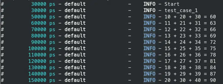
To run the test case and verify that everything works as expected, we can execute the run.py script from the directory it is located by simply typing in the terminal the following command.
python ./run.py -v
Note: A Customized logger has been used for better illustration in our output that is visible by providing the verbose -v option. In addition, since only one test case is defined, we don’t have to provide an option to specify it.
Finally, to verify our results in ModelSim, we could type the following command:
python ./run.py --gui

(Click the image to make it larger)
Conclusion
To conclude, we learned in this tutorial about how to incorporate and test Quartus IPs that reside in the IP catalog to VUnit. We employed a predefined IP. However, we can also integrate packaged customized IPs in this fashion in our VUnit environment.
Check out this VUnit tutorial if you haven’t already:
Getting started with VUnit

Hello,
First I’d like to say that this article is great! It shows the practical approach to real issue which engineer encounter when developing FPGA designs. However when I have a bit advanced design with i.e. Platform Designer System it contains a lot of Interconnect components and other libraries which has to be maually added to VUnit. Have anybody automated this work or it has to be done maually as showed in article?
Thank for any suggestions.
Damian