
When designing VHDL for safety-critical FPGA applications, it’s not enough to write testbenches at best-effort. You have to present proof that the module works as intended and without undesirable side-effects.
Formal verification techniques can help you map a requirement to a test, proving that your VHDL module conforms to the specification. It’s an instrumental tool for verifying healthcare applications or gaining DO-254 certification for airborne FPGA solutions.
To demystify formal verification, VHDLwhiz enlists the help of Michael Finn Jørgensen to write this guest post. Michael has substantial experience in the topic and shares many tips on his GitHub page.
The device under test in this article’s downloadable example comes from the existing tutorial:
How to make an AXI FIFO in block RAM using the ready/valid handshake
I’ll let Michael take over from here and explain formal verification to you in the rest of this blog post.
What is formal verification?
The aim of formal verification (FV) is to make sure your module works as intended!
FV is something you do as part of your development process before you synthesize your module. It is sometimes called “Property Checking”, which is a better description, I think.
In FV you specify the properties your module must have, and then the tool (called a “Satisfiability Solver”) will prove that your module satisfies the properties for all possible sequences of inputs.
In other words, the tool will look for any transition from a valid state (where all the properties are satisfied) to an invalid state (where one or more properties are violated). If there is no such transition, i.e. there is no way to transition to an invalid state, then the properties have been proven to be always satisfied.
The challenge in FV is to express the properties of your module in a language the tool can understand.
Formal verification is an alternative to manually written testbenches. The aim of both formal verification and manual testbenches is to eliminate bugs from the design, but formal verification does this by examining the properties and generating many different testbenches automatically.
The tools use two different methods:
- Bounded Model Checking (BMC). Starts from reset and examines a fixed number of clock cycles.
- Induction proof. Starts from an arbitrary valid state and verifies that any subsequent states are valid too.
The induction proof is more difficult to satisfy because it requires all properties to be stated, whereas BMC can be run with just a few properties and still give useful results.
Why use formal verification?
Formal verification is very good at catching hard-to-find bugs! That’s because formal verification automatically searches the entire space of possible inputs.
This is in contrast to traditional testbench writing that requires hand-crafting of stimuli. It’s practically impossible to explore the entire state space using manually written testbenches.
Additionally, when formal verification does find a bug, it will generate a very short waveform showing the bug and do this much faster than when running a simulation based on a manually written testbench. This short waveform is much easier to debug than a very long waveform that typically arises from simulation.
However, formal verification is not a substitute for testbench writing. In my experience, formal verification is well suited for unit testing, whereas it’s better to do integration testing using hand-crafted testbenches. That’s because the runtime of the formal verification increases exponentially with the size of the module.
There is indeed a learning curve associated with formal verification, but it is well worth the time, and I hope this blog post helps you get over this learning curve. You’ll complete your design sooner, and it will have fewer bugs!
How to write properties in PSL
When doing formal verification, you have to express your module’s properties using the Property Specification Language (PSL). The properties are typically located in a separate file with the ending .psl, and this file is used only during formal verification.
In this section, I’ll describe the main features of the PSL language in general terms, and in a later section, I’ll work you through a specific example.
There are three statements in PSL:
assertassumecover
You may already be familiar with the keyword assert when writing testbenches. This same keyword is used in PSL too, but with a slightly different syntax. The assert keyword is used to describe properties that this module promises to be always satisfied. In particular, the assert keyword is applied to outputs from the module, or possibly to the internal state as well.
The assume keyword is used to describe any requirements this module imposes on the inputs. In other words, the assume keyword is applied to inputs into the module.
The cover keyword is used to describe properties that must be possible to achieve in some way.
You may write regular VHDL code in the PSL file too, including signal declarations and processes (both synchronous and combinatorial).
The first line of the PSL file should be
vunit INSTANCE_NAME(ENTITY_NAME(ARCHITECTURE_NAME)) {
Here ENTITY_NAME and ARCHITECTURE_NAME refer to the module you’re verifying. The INSTANCE_NAME can be anything you like. The file should end with a closing brace: }.
The next line in the .psl file should be:
default clock is rising_edge(clk);
This avoids tediously having to refer to the clock signal in each of the property statements.
The syntax for the assert and assume statements is:
LABEL : assert always {PRECONDITION} |-> {POSTCONDITION}
LABEL : assume always {PRECONDITION} |-> {POSTCONDITION}
This statement reads as follows: If the PRECONDITION holds (in any clock cycle) then the POSTCONDITION must be satisfied in the same clock cycle.
There is another commonly used form:
LABEL : assert always {PRECONDITION} |=> {POSTCONDITION}
This statement reads as follows: If the PRECONDITION holds (in any clock cycle) then the POSTCONDITION must be satisfied in the next clock cycle.
Both forms are used extensively.
Within the PRE- and POST-CONDITIONS, you can use the keyword stable. This keyword means: The value in this clock cycle is the same as the value in the previous clock cycle.
Within the PRE- and POST-CONDITIONS, you can use sequences as well, by writing as follows:
{CONDITION_1 ; CONDITION_2}
This means that CONDITION_1 must be satisfied in this clock cycle and that CONDITION_2 must be satisfied on the next clock cycle.
The cover statement has the following syntax:
LABEL : cover {CONDITION}
We’ll see plenty of examples of all these statements in the worked example later in this blog.
Installing the required tools
Formal verification is supported by the leading tool vendors, including ModelSim. Unfortunately, the Student Edition of ModelSim does NOT* support formal verification. Indeed, you get the following error:
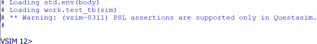
* Update, January 2023:
The Questa-Intel FPGA Starter Edition ModelSim equivalent now supports PSL assertions with the free license. Thanks to a helpful reader for notifying me about that!
Instead, there are open-source (free) tools that allow you to do formal verification. In this section, I’ll guide you through the installation process of these tools.
This guide assumes you’re running on a Linux platform. If you’re on a Windows platform, I recommend using the Windows Subsystem for Linux (WSL). The following guide is verified using Ubuntu 20.04 LTS.
Prerequisites
First, we must update the system to get the latest patches:
sudo apt update
sudo apt upgrade
Then we must install some additional development packages:
sudo apt install build-essential clang bison flex libreadline-dev \
                 gawk tcl-dev libffi-dev git mercurial graphviz   \
                 xdot pkg-config python python3 libftdi-dev gperf \
                 libboost-program-options-dev autoconf libgmp-dev \
                 cmake gnat gtkwave
Yosys et al.
git clone https://github.com/YosysHQ/yosys
cd yosys
make
sudo make install
cd ..

git clone https://github.com/YosysHQ/SymbiYosys
cd SymbiYosys
sudo make install
cd ..

git clone https://github.com/SRI-CSL/yices2
cd yices2
autoconf
./configure
make
sudo make install
cd ..
GHDL et al.
There are pre-packaged binaries for GHDL, but I recommend downloading the latest source files and compiling them as follows:
git clone https://github.com/ghdl/ghdl
cd ghdl
./configure --prefix=/usr/local
make
sudo make install
cd ..

git clone https://github.com/ghdl/ghdl-yosys-plugin
cd ghdl-yosys-plugin
make
sudo make install
cd ..
Download the example project
The next section of this article guides you through implementing formal verification for an existing VHDL project. You can download the complete code by entering your email address in the form below.
Worked example with formal verification
The following section will describe how to formally verify the axi_fifo module written about previously on this blog.
To start on the formal verification, we need to ask ourselves, what properties does the FIFO have? I have identified four categories of properties:
- Reset handling: That the module wakes up in a well-defined state after reset.
- FIFO full and empty signaling: This verifies that the FIFO correctly indicates the full and empty conditions.
- AXI protocol: That the module satisfies the requirements of the AXI valid/ready handshake.
- FIFO ordering: That the FIFO doesn’t drop/duplicate/reorder elements that pass through it.
I’ll discuss each of these properties in the following.
Reset handling
First, we declare that the module expects reset to be asserted for one clock cycle:
f_reset : assume {rst};
Note here the absence of the keyword always. Without the always keyword, the statement only holds for the very first clock cycle.
It is customary (and very useful) to give each formal statement a label. When running the formal verification, the tool will refer back to these labels when reporting any failures. I use the convention of preceding all such labels with f_.
Then we state that the FIFO must be empty after reset:
f_after_reset_valid : assert always {rst} |=> {not out_valid};
f_after_reset_ready : assert always {rst} |=> {in_ready};
f_after_reset_head  : assert always {rst} |=> {count = 0};
Note that it is possible to reference internal signals in the module and not just ports. Here we reference count, which is the current filling level, i.e. number of elements currently in the FIFO. That’s possible because we refer to the architecture name in the first line of the PSL file.
We could alternatively have a separate process in the PSL file counting the number of elements going in and out of the FIFO. While that is to be preferred, I’m going to use the internal count signal to keep this blog post short and to the point.
FIFO full and empty signaling
The way the AXI FIFO signals full and empty is with the out_valid and in_ready signals. The out_valid signal is asserted whenever the FIFO is not empty, and the in_ready signal is asserted whenever the FIFO is not full. Let’s check these properties:
f_empty : assert always {count = 0} |-> {not out_valid};
f_full : assert always {count = ram_depth-1} |-> {not in_ready};
AXI protocol
The valid/ready AXI handshake states that data transfer only happens when both valid and ready are asserted simultaneously. One typical error when working with this protocol is asserting valid (and accompanying data) and not checking ready. In other words, if valid is asserted and ready is not, then valid should remain asserted the next clock cycle, and data should remain unchanged. That applies both to data going into the FIFO and the data coming out of the FIFO. For data entering the FIFO, we use the assume keyword, and for data coming out of the FIFO, we use the assert keyword.
f_in_data_stable : assume always
   {in_valid and not in_ready and not rst} |=>
   {stable(in_valid) and stable(in_data)};

f_out_data_stable : assert always
   {out_valid and not out_ready and not rst} |=>
   {stable(out_valid) and stable(out_data)};
Note here the use of the stable keyword in combination with the |=> operator. These statements reference two consecutive clock cycles. On the first clock cycle, it checks whether valid is asserted and ready is not asserted. Then on the next (second) clock cycle (indicated by the |=> operator), the values of valid and data should be the same as the previous (i.e. first) clock cycle.
Secondly, for the AXI protocol we require that the ready signal is stable. What this means is if the FIFO can accept data (ready is asserted) but no data is input (valid is not asserted), then on the next clock cycle ready should remain asserted.
f_out_ready_stable : assume always
   {out_ready and not out_valid and not rst} |=>
   {stable(out_ready)};

f_in_ready_stable : assert always
   {in_ready and not in_valid and not rst} |=>
   {stable(in_ready)};
FIFO ordering
Another important property of a FIFO is that data does not get duplicated/deleted/swapped. Expressing this property in PSL is quite complex, and this is the hardest part of this formal verification. Let’s walk through this property carefully step-by-step.
We can say in general that if any data D1 enters the FIFO before some other data D2, then on the output side the same data D1 must leave the FIFO before D2 does.
To express this in PSL we need some auxiliary signals: f_sampled_in_d1, f_sampled_in_d2, f_sampled_out_d1, and f_sampled_out_d2. These signals are cleared at reset and asserted whenever D1 or D2 enters or leaves the FIFO. Once asserted, these signals remain asserted.
So we express the FIFO ordering property in two parts: First an assumption that once D2 enters the FIFO, then D1 has already previously entered:
f_fifo_ordering_in : assume always
   {f_sampled_in_d2} |->
   {f_sampled_in_d1};
And secondly, an assertion that once D2 leaves the FIFO, then D1 has already previously left:
f_fifo_ordering_out : assert always
   {f_sampled_out_d2} |->
   {f_sampled_out_d1};
We still need to declare and populate the sampling signals referenced above. We do this as follows for the input sampling signals:
signal f_sampled_in_d1  : std_logic := '0';
signal f_sampled_in_d2  : std_logic := '0';

...

p_sampled : process (clk)
begin
   if rising_edge(clk) then
      if in_valid then
         if in_data = f_value_d1 then
            f_sampled_in_d1 <= '1';
         end if;
         if in_data = f_value_d2 then
            f_sampled_in_d2 <= '1';
         end if;
      end if;

      if out_valid then
         if out_data = f_value_d1 then
            f_sampled_out_d1 <= '1';
         end if;
         if out_data = f_value_d2 then
            f_sampled_out_d2 <= '1';
         end if;
      end if;

      if rst = '1' then
         f_sampled_in_d1  <= '0';
         f_sampled_in_d2  <= '0';
         f_sampled_out_d1 <= '0';
         f_sampled_out_d2 <= '0';
      end if;
   end if;
end process p_sampled;
Here we are referencing two other signals, f_value_d1 and f_value_d2. They contain the data values D1 and D2. These signals can contain any arbitrary values, and there is a special way of indicating this to the formal verification tool:
signal f_value_d1 : std_logic_vector(ram_width - 1 downto 0);
signal f_value_d2 : std_logic_vector(ram_width - 1 downto 0);
attribute anyconst : boolean;
attribute anyconst of f_value_d1 : signal is true;
attribute anyconst of f_value_d2 : signal is true;
The anyconst attribute is recognized by the formal verification tool. It indicates that the tool can insert any constant value in its place.
With the above, we have specified the properties of the FIFO.
Running formal verification
Before we can actually run the formal verification tool, we need to write a small script axi_fifo.sby:
[tasks]
bmc

[options]
bmc: mode bmc
bmc: depth 10

[engines]
smtbmc

[script]
ghdl --std=08 -gram_width=4 -gram_depth=8 axi_fifo.vhd axi_fifo.psl -e axi_fifo
prep -top axi_fifo

[files]
axi_fifo.psl
axi_fifo.vhd
The section [tasks] states that we want to Bounded Model Checking. The section [options] specifies that BMC should run for 10 clock cycles. The default is 20. The section [engines] chooses which of several different solvers to use. There can be differences in execution speed of the different possible engines, depending on your particular design. For now, just leave this value unchanged.
The [script] section is the interesting part. Here we specify the VHDL standard (2008), the generics’ values, the files to process, and the top-level entity’s name. Finally, the [files] section contains the file names again.
With this script ready, we can run the actual formal verification using this command:
sby --yosys "yosys -m ghdl" -f axi_fifo.sby
Running the formal verification tool ends with the unceremonious statement:
[axi_fifo_bmc] DONE (PASS, rc=0)
And that just means that all the properties we’ve specified are satisfied with all arbitrary inputs for up to 10 clock cycles. Increasing the depth leads to longer execution times for the solver. However, note that the depth is greater than the FIFO’s depth, meaning that the BMC will encounter a FIFO full situation for some input sequences. If we had only chosen, say, 5 clock cycles, the formal verification would never encounter a FIFO full, and would not catch any bugs related to that.
It is possible to prove the properties are satisfied for all clock cycles using the Induction Proof. However, that requires more work writing the properties. The challenge is that so far, we’ve just written some properties. But for induction, we need to specify all properties (or at least sufficiently many). That would be quite time-consuming, so instead, I’ll discuss an alternative strategy for increasing our confidence.
Mutation
So now we’ve described some of the properties that the axi_fifo module must satisfy, and our tool quickly confirms those properties, i.e. proves they are satisfied. But we might still have this uneasy feeling: Are we sure there are no bugs? Have we really expressed all the properties of the axi_fifo module?
To help answer these questions and to get more confidence in the completeness of the properties specified, we can apply a technique called mutation: We purposefully make a small change in the implementation, i.e. deliberately introduce a bug, and then see if the formal verification will catch the bug!
One such change could be to remove some of the logic controlling the out_valid signal. For instance, we could comment out these three lines:
if count = 1 and read_while_write_p1 = '1' then
  out_valid_i <= '0';
end if;
When we run the formal verification now we get a failure with the message
Assert failed in axi_fifo: i_axi_fifo.f_out_data_stable
Writing trace to VCD file: engine_0/trace.vcd
Using the tool GTKwave we can view the accompanying waveform, and it looks as follows:
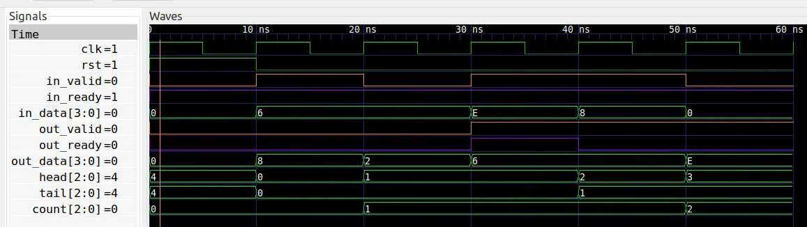
Here we see that at 40 ns, the out_valid signal should go to zero, but it does not. The assertion that fails is at 50 ns, where out_valid remains high, but the out_data signal changes, indicating duplicate data. The duplicated data was not actually transmitted in this particular trace because out_ready is low at 40 ns, but the formal verification detects the bug nevertheless.
Cover statement
Let’s finally turn to a different application of the formal verification tool: Cover statement. The purpose of the cover statement is to check whether there is a sequence of inputs that satisfies a particular property. Since we’re dealing with a FIFO, let’s see if we can fill it completely and then empty it again. This can be expressed in a single cover statement:
f_full_to_empty : cover {
   rst = '1';
   rst = '0'[*];
   rst = '0' and count = ram_depth-1;
   rst = '0'[*];
   rst = '0' and count = 0};
That’s quite a mouth-full! Note the semi-colons within the {}. For readability, I’ve placed each section on a separate line. This cover statement reads as follows: Look for a sequence of inputs that satisfies:
- Reset is asserted for one clock cycle.
- Any number of clock cycles (where reset is not asserted) may then pass.
- One clock cycle where reset is not asserted and the FIFO is full.
- Any number of clock cycles (where reset is not asserted) may then pass.
- One clock cycle where reset is not asserted and the FIFO is empty.
So the syntax [*] means repeat (zero or more times) the preceding condition. In line 3, we could have removed the condition rst = '0' in front of [*]. The results will be the same. The reason is that the formal verifier will try to find the shortest sequence that satisfies the cover statement, and asserting reset while filling the FIFO will just delay that. However, when emptying the FIFO in line 5, it is essential that reset is not asserted.
To run the formal verifier now, we have to make a small modification to the script axi_fifo.sby. Replace the top sections with the following:
[tasks]
bmc
cover

[options]
bmc: mode bmc
bmc: depth 10
cover: mode cover
Now the solver will run the BMC and then run the cover analysis. In the output you’ll see these two lines:
Reached cover statement at i_axi_fifo.f_full_to_empty in step 15.
Writing trace to VCD file: engine_0/trace5.vcd
This means that the cover statement can indeed be satisfied with a sequence of 15 clock cycles, and the solver has generated a waveform specifically for this cover statement:
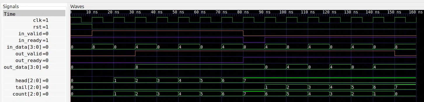
Here we see at 80 ns the FIFO is full and in_ready is de-asserted. And at 150 ns the FIFO is empty and out_valid is de-asserted. Note how during the period 30 ns to 80 ns that out_ready is held low. That is necessary to ensure the FIFO is filling up.
If we replace the condition count = ram_depth-1 with count = ram_depth, the cover statement cannot be satisfied. The tool then reports an error.
Unreached cover statement at i_axi_fifo.f_full_to_empty
So the error message contains the label of the cover statement that fails. That is one reason why labels are so useful! We interpret the above error as stating that the FIFO can never hold ram_depth number of elements. This is exactly as stated in the original AXI FIFO blog post.

Ok. Thank you so much for this post. I just tried some of it. I love using Formal Verification to generate waveforms and test properties! So much neater than how I was testing before.
It’s fantastic! One gets a much better understanding of the behaviour of your system as well.
My only gripe is that the tools don’t quite seem to support custom VHDL libraries. I know how to use libraries in GHDL but not with SymbiYosys with the yosys-ghdl plugin script for the sby file.
That and GHDL does not support all of the PSL such as [*2..14]. Managed to do some work arounds but it would have been much nicer if I didn’t have to.
Still, hard to imagine going back to the old ways if one can use PSL.
Thanks!
Now for C++…
> That and GHDL does not support all of the PSL such as [*2..14]. Managed to do some work arounds but it would have been much nicer if I didn’t have to.
What do you mean with that? GHDL already supports ranges in SERE repetition or LTL operators:
For example:
assert always {req} |=> {busy[=2 to 4]; done};Please see in my https://github.com/tmeissner/psl_with_ghdl project for more examples.
The only dawback is that these ranges have to be static numerical literals. Maybe that will be enhanced in future.
Good day. I was mistook the syntax. I was working from the Wiki article on PSL.
[*2..14] vs [*2 to 14]
Yes. It would be great if the ranges could be dynamic.
Thanks!
Enjoy a lot this tutorial. Encourage me to think of aspects I did not think about before.
Can you explain the application aspect of formal verification vs. random verification.
When I should use each of them? is there a case we ‘ll use both?
Thank you.
I noticed that sby was not running ghdl properly for my system (WSL2: Ubuntu-18.04.6 LTS). I had to remove the semicolons from the command to execute it properly:
It worked after that, so hopefully others may find it helpful.
This is a wonderful tutorial and a great starting point!
Thanks for this post. I’ve just successfully built the tools on the suggested OS. I had two minor modifications to make, to tidy up the build. (Installing WSL bricked my machine so I went to VirtualBox as VMWare seems to be inaccessible these days.)
1. Removed ‘python’ from the install command line
“`
apt install build-essential clang bison flex libreadline-dev \
gawk tcl-dev libffi-dev git mercurial graphviz \
xdot pkg-config python3 libftdi-dev gperf \
libboost-program-options-dev autoconf libgmp-dev \
cmake gnat gtkwave
“`
Had to perform a `git submodule init` for yosys.
“`
git clone https://github.com/YosysHQ/yosys
cd yosys
# Added next line
git submodule update –init
make
sudo make install
cd ..
“`
Next I have to run the tools.
Thank you!