VUnit is one of the most popular open-source VHDL verification frameworks available today. It combines a Python test suite runner with a dedicated VHDL library to automate your testbenches.
To give you this free VUnit tutorial, VHDLwhiz enlists Ahmadmunthar Zaklouta, who is behind the rest of this article, including the simple VUnit example project that you can download and run on your computer.
* Update
Check out VHDLwhiz's new VUnit course with 15 video lessons!
Course: VUnit for structured testbench and advanced BFM design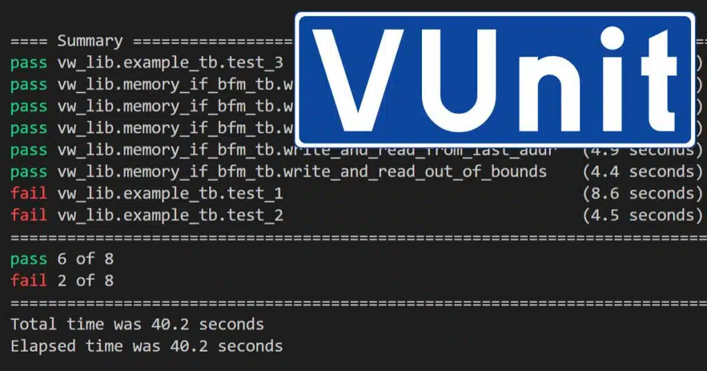
Now, let’s give the word to Ahmad!
This tutorial aims to demonstrate the use of the VUnit framework in the verification process of your design. It will guide you through the process of setting up VUnit, creating the VUnit testbench, using the VUnit check library, and running VUnit tests in ModelSim. It also demonstrates some verification techniques.
Overview
This article contains multiple screenshots. Click the images to make them larger!
Use the sidebar to navigate the outline for this tutorial, or scroll down and click the pop-up navigation button in the top-right corner if you are using a mobile device.
Requirements
This tutorial assumes having this software is installed on a Windows machine:
- Intel ModelSim
- Please refer to this article for how to install ModelSim for free.
- ModelSim should be in your PATH.
- Python 3.6 or higher.
- Download Python
- Python should be in your PATH.
- GIT (optional).
- Windows terminal (optional)
It also assumes having basic VHDL knowledge and ModelSim skills.
Installing
- Getting VUnit:
- If you have GIT, you can clone it from GitHub to your C drive:
git clone --recurse-submodules https://github.com/VUnit/vunit.git
- Otherwise, you can download it as a Zip from GitHub and extract it to your C drive:
python setup.py install
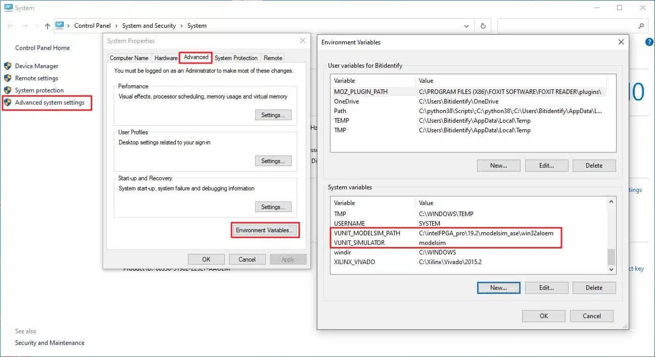
- Configuring VUnit:
- Add environment variables to your system as below.
VUNIT_MODELSIM_PATH: path to ModelSim in your machine.VUNIT_SIMULATOR: ModelSim
Download the example project
You can download the example project and VHDL code using the form below.
Extract the Zip to C:\vunit_tutorial.
Introduction
VUnit is a testing framework for HDL that eases the verification process by providing a test-driven workflow “test early and often” and toolbox for test running automation and administration. It is an advanced framework with extensive rich features, but yet easy to use and adapt. It is entirely open-source and can be easily incorporated into traditional testing methodologies.
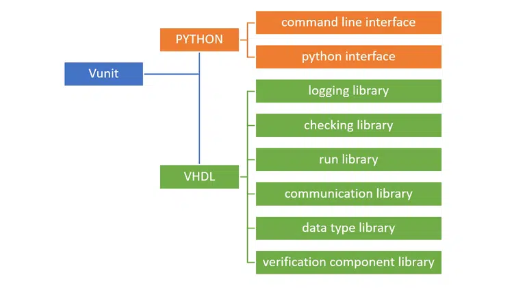
VUnit consists of two main components:
- Python library: provides tools that help with test automation, administration, and configuration.
- VHDL library: a set of libraries that helps with common verification tasks.
The VHDL part consists of six libraries, as shown in the diagram below. This tutorial will use the logging and checking libraries.

Design under test
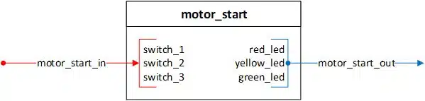
The design used in this tutorial, named motor_start, implements a starting procedure for a particular motor and drives 3 LEDs representing the motor’s status.
The interface consists of an input record motor_start_in with 3 elements (3 switches as inputs) and an output record motor_start_out with 3 elements (3 LEDs RED, YELLOW, GREEN as outputs).
Some motors need initialization in the beginning before you can start using them. Our motor start-up procedure has three steps:
- Loading configuration
- Calibration
- Rotation
Startup sequence
Here follows the motor startup sequences and the meaning of the LED indicators.
- RED_LED represents loading configuration.
- Turn on switch_1.
- The RED_LED will start blinking 5 times.
- Wait until the RED_LED stops blinking and is constantly lighting.
- YELLOW_LED represents loading calibration.
- Now you can turn on switch_2.
- When switch_2 is turned ON, YELLOW_LED will start constantly lighting after 5 clock cycles, lasting 10 clock cycles. And after that, YELLOW_LED and RED_LED will turn OFF.
- GREEN_LED indicates that the motor is rotating.
- Now, the motor is ready to use. Each time switch_3 is turned ON, GREEN_LED will start constantly lighting until switch_3 is turned OFF.
- Any violation to this sequence will result in all 3 LEDs constantly lighting until all switches are turned OFF, and the sequence can be started again.
Testbench development
This part of the tutorial consists of the following subsections:
- Setting up the Python running script
- Setting up the VUnit skeleton
- Setting up the testbench
Setting up the Python running script run.py
Each VUnit project needs a top-level python script run.py that acts as an entry point to the project, and it specifies all the VHDL design, testbench, and library sources.
This file is usually existing in the project directory. The directory tree used in this tutorial is as below:
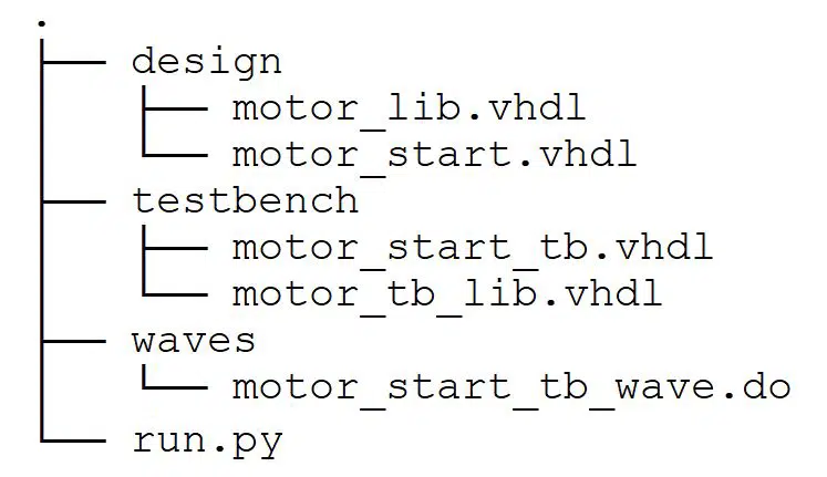
In the run.py file, we need to do three things:
1 – Fetch the path where this file exists and specify the path for design and testbench files.
# ROOT
ROOT = Path(__file__).resolve().parent
# Sources path for DUT
DUT_PATH = ROOT / "design"
# Sources path for TB
TEST_PATH = ROOT / "testbench"
2 – Create the VUnit instance.
This will create a VUnit instance and assign it to a variable named VU. Then we can use VU to create libraries and various tasks.
# create VUnit instance
VU = VUnit.from_argv()
VU.enable_location_preprocessing()
3 – Create libraries and add VHDL sources to them.
I like to separate the design part from the testbench part. Therefore, we will create two libraries: design_lib and tb_lib.
# create design library
design_lib = VU.add_library("design_lib")
# add design source files to design_lib
design_lib.add_source_files([DUT_PATH / "*.vhdl"])

# create testbench library
tb_lib = VU.add_library("tb_lib")
# add testbench source files to tb_lib
tb_lib.add_source_files([TEST_PATH / "*.vhdl"])
The rest of the file is a configuration for ModelSim to use the wave.do file if it exists.
Note: here, I use the *.vhdl extension. You might need to modify it if you use *.vhd.
If you like this working structure, then you don’t need to change this file at all. Whenever you start a new project, just copy it to your project directory. However, if you prefer a different directory structure, you need to modify the paths to comply with your working structure.
Now, whenever we use this file, VUnit will automatically scan for VUnit testbenches in your project, determine the compile order, create the libraries and compile sources into them, and optionally run the simulator with all or specific test cases.
Isn’t that awesome? 😀
Setting up the VUnit skeleton
To create a VUnit testbench, we need to add some specific code to our testbench file motor_start_tb, as explained in this subsection.
1 – Add the libraries as follow.
First, we need to add the VUnit library VUNIT_LIB and its context: VUNIT_CONTEXT, so that we have access to the VUnit functionality as follows:
LIBRARY VUNIT_LIB;
CONTEXT VUNIT_LIB.VUNIT_CONTEXT;
Second, we need to add the design and testbench libraries DESIGN_LIB and TB_LIB so that we have access to our DUT and packages as follows:
LIBRARY DESIGN_LIB;
USE DESIGN_LIB.MOTOR_PKG.ALL;

LIBRARY TB_LIB;
USE TB_LIB.MOTOR_TB_PKG.ALL;
The DUT has two packages; one for design: motor_pkg and the other for testbench elements motor_tb_pkg. They are trivial packages that I created because this is usually how big projects are structured. I want to show how VUnit deals with that.
motor_startandmotor_pkgwill be compiled intoDESIGN_LIB.motor_start_tbandmotor_tb_pkgwill be compiled intoTB_LIB.
2 – Add runner configuration to the entity as follows:
ENTITY motor_start_tb IS

GENERIC(runner_cfg : string := runner_cfg_default);

END ENTITY motor_start_tb;
runner_cfg is a generic constant that lets the python test runner control the testbench. That is, we can run tests from the python environment. This generic is mandatory and does not change.
3 – Add the VUnit testbench skeleton to our testbench as follows:
ARCHITECTURE tb OF motor_start_tb IS
test_runner : PROCESS
BEGIN
-- setup VUnit
test_runner_setup(runner, runner_cfg);

test_cases_loop : WHILE test_suite LOOP

-- your testbench test cases here

END LOOP test_cases_loop;

test_runner_cleanup(runner); -- end of simulation
END PROCESS test_runner;

END ARCHITECTURE tb;
test_runner is the main controlling process for the testbench. It always starts with the procedure test_runner_setup and finishes with the procedure test_runner_cleanup. The simulation lives between these two procedures. test_cases_loop is our test suits where all our test cases take place.
To create a test case, we use VUnit’s run function within an If statement as follows:
IF run("test_case_name") THEN
-- test case code here

ELSIF run("test_case_name") THEN
-- test case code here

END IF;
Then we can run all or specific test cases from the Python environment by simply calling them with the name we specified in the call to run.
Setting up the testbench
Here, we start by adding the required signals to communicate with the DUT, as shown below:
--------------------------------------------------------------------------
-- TYPES, RECORDS, INTERNAL SIGNALS, FSM, CONSTANTS DECLARATION.
--------------------------------------------------------------------------
-- CONSTANTS DECLARATION --
-- simulation constants
CONSTANT C_CLK_PERIOD : time := 10 ns;

-- INTERNAL SIGNALS DECLARATION --
-- DUT interface
SIGNAL clk             : STD_LOGIC := '0';
SIGNAL reset           : STD_LOGIC := '1';
SIGNAL motor_start_in  : MOTOR_START_IN_RECORD_TYPE :=
  (switch_1 => '0', switch_2 => '0', switch_3 => '0');

SIGNAL motor_start_out : MOTOR_START_OUT_RECORD_TYPE;

-- simulation signals
SIGNAL led_out : STD_LOGIC_VECTOR(2 DOWNTO 0) := (OTHERS => '0');
Note: It is a good practice to initialize the signals with an initial value.
Next, instantiate the DUT like this:
--------------------------------------------------------------------------
-- DUT INSTANTIATION.
--------------------------------------------------------------------------
motor_start_tb_inst : ENTITY DESIGN_LIB.motor_start(rtl)
  PORT MAP(
    clk             => clk,
    reset           => reset,
    motor_start_in  => motor_start_in,
    motor_start_out => motor_start_out
  );
Note: I grouped the input ports and output ports in records. I find this beneficial in big projects because it makes the entities and instantiations less cluttered.
And finally, drive clk, reset, and led_out as shown here:
--------------------------------------------------------------------------
-- SIGNAL DEFINITION OF UNUSED OUTPUT PORTS AND FIXED SIGNALS.
--------------------------------------------------------------------------
led_out(0) <= motor_start_out.red_led;
led_out(1) <= motor_start_out.yellow_led;
led_out(2) <= motor_start_out.green_led;

--------------------------------------------------------------------------
-- CLOCK AND RESET.
--------------------------------------------------------------------------
clk   <= NOT clk after C_CLK_PERIOD / 2;
reset <= '0' after 5 * (C_CLK_PERIOD / 2);
Test case development
Now let us go back to our DUT and start the actual work by developing some test cases. I will present two scenarios:
Design engineer scenario: from the designer’s point of view, the designer himself performing the verification. In this scenario, which usually happens during the development phase, the designer can access the code. This scenario will show how VUnit helps us “test early and often”.
Verification engineer scenario: the design (DUT) is treated as a black box. We only know the external interface and test requirements.
We will also look at these three verification techniques:
- Driver and checker within the test case.
- Driver and controlled checker within the test case.
- Driver within the test case and self-checking checker.
Let’s start with the first technique and get back to the last two methods later in this article.
Driver and checker within the test case
This is the most straightforward approach. The driver and the checker are inside the test case itself, we implement the driving and checking operations within the test case code.
Let us assume that we developed the RED_LED functionality as below:
WHEN SWITCH_1_ON =>
  IF (motor_start_in.switch_1 = '0' OR
      motor_start_in.switch_2 = '1' OR
      motor_start_in.switch_3 = '1') THEN
    state = WAIT_FOR_SWITCHES_OFF;
  ELSIF (counter = 0) THEN
    led_s.red_led <= '1';
    state         <= WAIT_FOR_SWITCH_2;
  ELSE
    led_s.red_led <= NOT led_s.red_led;
  END IF;
And now, we want to verify our design before we proceed to develop the rest of the functionality.
To do that, we use VUnit’s run function inside the test_suite to create a test case for verifying the output of turning ON switch_1, as shown below:
IF run("switch_1_on_output_check") THEN
  info("------------------------------------------------------------------");
  info("TEST CASE: switches_off_output_check");
  info("------------------------------------------------------------------");
  -- code for your test case here.
This will create a test case named “switch_1_on_output_check”
Note: info is a VUnit procedure from the logging library that prints to the transcripts screen and the terminal. We will use it to display the test result.
Now, we will write the code for this test case. We will use VUnit’s checking subprograms to do that.
We know that RED_LED will blink 5 times after switch_1 is turned ON, so we create a VHDL For loop and perform the checking inside it.
The check procedure performs a check on the specific parameters we provide. It has many variants, and here, I used several of them for demonstration purposes.
check(expr => motor_start_out.red_led = '1',
      msg  => "Expect red_led to be ON '1'");
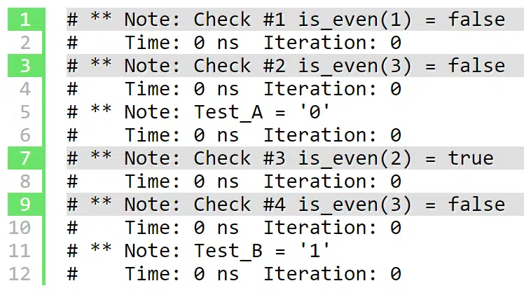
Here, it will test if RED_LED is ‘1’ at this point of simulation time and print a message to the console:
# 35001 ps - check - PASS - red_led when switch_1 on (motor_start_tb.vhdl:192)
Note that it tells us if it’s a PASS or an ERROR, and the timestamp when this check happened, along with the file name and line number where this check is.
Another way is to use the check_false procedure. Here, we use it for checking that YELLOW_LED is ‘0’:
check_false(expr => ??motor_start_out.yellow_led,
            msg  => result("for yellow_led when switch_1 on"));
Here, we use VUnit’s result function to improve the message. The printout will look like this:
# 35001 ps - check - PASS - False check passed for yellow_led when switch_1 on
#                           (motor_start_tb.vhdl:193)
Note that it prints extra information about the check type: “False check passed”.
Yet another way is to use check_equal. Here, we use it for testing that GREEN_LED is ‘0’:
check_equal(got      => motor_start_out.green_led,
            expected => '0',
            msg      => result("for green_led when switch_1 on"));
Here, we provided an extra parameter ‘0’ for the comparison. The resulting printout is:
# 35001 ps - check - PASS - Equality check passed for green_led when switch_1 on -
#                           Got 0. (motor_start_tb.vhdl:194)
Now, we know that after one clock cycle, RED_LED will turn OFF, and the other LEDs will stay off too. We can use check_equal to check all of them simultaneously, as shown below:
check_equal(led_out, STD_LOGIC_VECTOR'("000"),
            result("for led_out when switch_1 on"), warning);
Note the use of the qualifier STD_LOGIC_VECTOR'("000"), so the values are not ambiguous for the procedure. Also, we specified the level of this check to be WARNING, meaning that if this check fails, it will issue a warning instead of throwing an error. The output will look like this:
#  45001 ps - check - PASS - Equality check passed for led_out when switch_1 on -
#                            Got 000 (0). (motor_start_tb.vhdl:197)
This is the code for the complete test case:
WAIT UNTIL reset <= '0';
WAIT UNTIL falling_edge(clk);
motor_start_in.switch_1 <= '1';  -- turn on switch_1
FOR i IN 0 TO 4 LOOP
  WAIT UNTIL rising_edge(clk);
  WAIT FOR 1 ps;
  check(expr => motor_start_out.red_led = '1',
        msg  => "Expect red_led to be ON '1'");

 check_false(expr => ??motor_start_out.yellow_led,
             msg  => result("for yellow_led when switch_1 on"));

 check_equal(got      => motor_start_out.green_led,
             expected => '0',
             msg      => result("for green_led when switch_1 on"));

  WAIT UNTIL rising_edge(clk);
  WAIT FOR 1 ps;
  check_equal(led_out, STD_LOGIC_VECTOR'("000"),
              result("for led_out when switch_1 on"), warning);
END LOOP;
info("===== TEST CASE FINISHED =====");
Test case running
Now it is time to run our test case. We can run the tests in the terminal or in the simulator GUI.
Running a test in the terminal
To do that, start by opening a new terminal (CMD, PowerShell, Windows Terminal) and navigate to the vunit_tutorial directory where the run.py file is located.
To run the test case, simply type:
python .\run.py *switch_1_on_output_check
VUnit will compile all the VHDL files in the correct order and parse them, looking for VUnit testbenches. And then, VUnit will look inside those files, searching for a run function with the “switch_1_on_output_check” test case name to execute it.
Note: we put the * wildcard symbol before the test case to match its full name, which is:
tb_lib.motor_start_tb.switch_1_on_output_check
We can do that because the VUnit command-line interface accepts wildcards.
The resulting printout after simulating is:
Starting tb_lib.motor_start_tb.switch_1_on_output_check
Output file: C:\vunit_tutorial\vunit_out\test_output\tb_lib.motor_start_tb.
switch_1_on_output_check_6df3cd7bf77a9a304e02d3e25d028a92fc541cf5\output.txt
pass (P=1 S=0 F=0 T=1) tb_lib.motor_start_tb.switch_1_on_output_check (1.1 seconds)

==== Summary ==========================================================
pass tb_lib.motor_start_tb.switch_1_on_output_check (1.1 seconds)
=======================================================================
pass 1 of 1
=======================================================================
Total time was 1.1 seconds
Elapsed time was 1.1 seconds
=======================================================================
All passed!
We can see that one test has run, and it was a PASS.
Note that VUnit has created a vunit_out folder in the project directory. Inside this folder, there is a folder named test_output that has reports about the tests.
Above, we got only the final test result without details about each check, but the VUnit command-line tool provides several switches for running tests. To get more information about what’s going on during simulation, we can use the verbose switch -v:
python .\run.py *switch_1_on_output_check -v
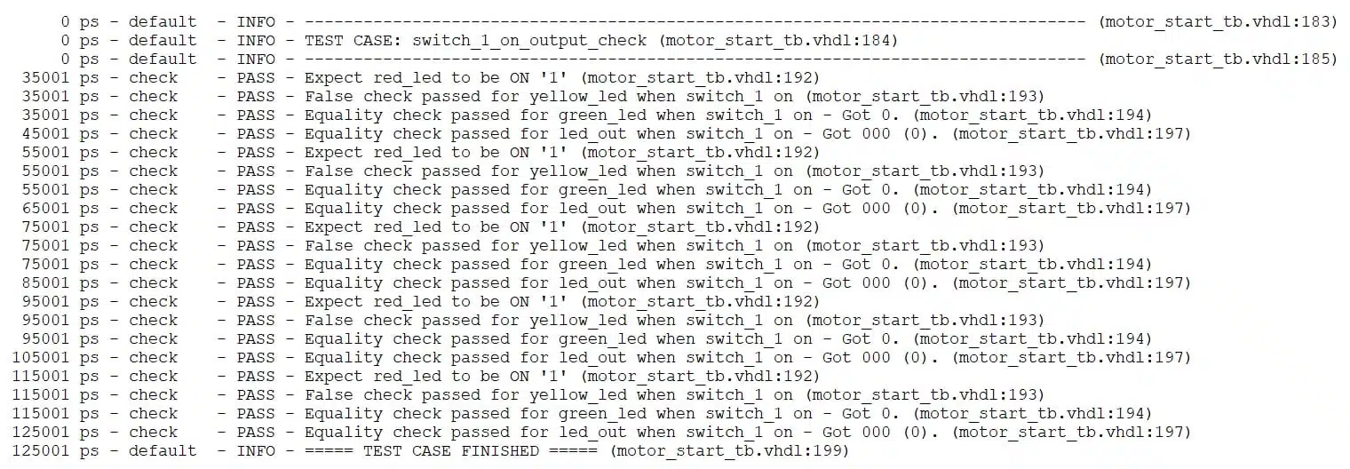
The verbose printout will look like this:
Other useful switches are:
-l, --list: List all test cases.
--clean: Delete the output folder first and then runs the test.
--compile: This switch is useful if you want to compile without running tests to check for errors, for example.
Running a test in the simulator GUI
Often a visual inspection of the wave is required. VUnit provides an automated way to run tests in the simulator by using the GUI switch -g. VUnit will do all the compilation and launch ModelSim (the simulator we configured) with the test case requested and add the signals to the wave window, given that a wave.do file is available.
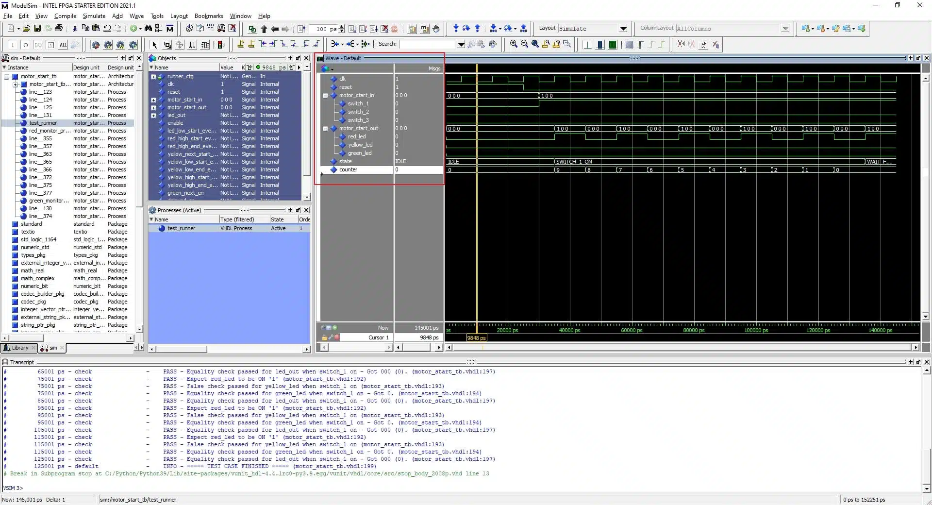
python .\run.py *switch_1_on_output_check -g
Now, VUnit will launch ModelSim for this specific test case, open the waveform window, and add the signals because I already have the motor_start_tb_wave.do inside the waves folder.
Note: You can customize the waveform as you want, but you must save the waveform format file inside the waves folder with this name convention testbench_file_name_wave.do so it can be loaded when VUnit launches ModelSim.
Suppose you change your code after discovering errors and want to rerun this test case. In that case, you can type in ModelSim’s transcript window: vunit_restart, That will cause VUnit to recompile, restart, and rerun the simulation.
Driver and controlled checker within the test case
So far, we have learned how to set up a VUnit testbench and develop and run the test case. In this section, we will develop more test cases from the verification engineer’s point of view, using a different verification approach and VUnit checker library.
Unlike the previous test case, this approach has the driver inside the test case and the checker outside, but the test case still controls it.
Let’s assume we’ve got this verification requirement:
- Verify the output after turning ON switch_2 while switch_1 is ON and RED_LED is lighting.
From the DUT section, we know that:
- When switch_2 is turned ON, YELLOW_LED will start constantly lighting after 5 clock cycles for 10 clock cycles, and after that, YELLOW_LED and RED_LED will turn OFF.
We will use VUnit’s check_stable procedure to verify that:
- YELLOW_LED is ‘0’ from the start until switch_2 is ON.
- YELLOW_LED is ‘1’ for 10 clock cycles.
We will use VUnit’s check_next procedure to verify that:
- YELLOW_LED is ‘1’ after 5 clock cycles from turning switch_2 on.
check_stable: verify that signal[s] are stable inside a window that starts with a start_event signal pulse and finishes with an end_event signal pulse.
check_next: verify that signal = ‘1’ after a number of clock cycles after a start_event signal pulse.
start_event and end_event signals will be controlled from the test case.
We start by adding required signals for check_stable and check_next procedures as follows:
-- VUnit signals
SIGNAL enable                  : STD_LOGIC := '0';
-- for yellow_led
SIGNAL yellow_next_start_event : STD_LOGIC := '0';
SIGNAL yellow_low_start_event  : STD_LOGIC := '0';
SIGNAL yellow_low_end_event    : STD_LOGIC := '0';
SIGNAL yellow_high_start_event : STD_LOGIC := '0';
SIGNAL yellow_high_end_event   : STD_LOGIC := '0';
Then we create a new test case inside the test_suite using VUnit’s run function as follows:
ELSIF run("switch_2_on_output_check") THEN
  info("------------------------------------------------------------------");
  info("TEST CASE: switch_2_on_output_check");
  info("------------------------------------------------------------------");
We create a start_event for YELLOW_LED’s low state for using with the check_stable procedure as follows:
WAIT UNTIL reset <= '0';
-- out of reset
enable <= '1';
pulse_high(clk, yellow_low_start_event);
WAIT FOR C_CLK_PERIOD * 3;
The enable signal activates the check_stable and check_next procedures, and we want to enable them from the beginning.
pulse_high is a trivial procedure from motor_tb_pkg that waits for the next rising clock edge and pulses a signal for one clock cycle. In this case, it is yellow_ low_start_event.
Now, we turn switch_1 ON and wait until RED_LED is lighting constantly, and then we turn switch_2 ON:
-- turn ON switch_1
motor_start_in.switch_1 <= '1';
-- wait until RED_LED finished
WAIT FOR C_CLK_PERIOD * 12;
-- turn ON switch_2
motor_start_in.switch_2 <= '1';
Now we know that after 5 clock cycles, YELLOW_LED will be ‘1’. Therefore, we create a start_event for YELLOW_LED to use with the check_next procedure:
-- after 5 clk cycles YELLOW_LED will light
-- next_start_event for YELLOW_LED high
pulse_high(clk, yellow_next_start_event); -- 1st clk cycle
Similarly, we create an end_event for YELLOW_LED’s low state to use with the check_stable procedure:
WAIT FOR C_CLK_PERIOD * 3;

-- end event for YELLOW_LED low
pulse_high(clk, yellow_low_end_event);  -- 5th clk cycle
Now, YELLOW_LED will be high for 10 clock cycles. Therefore, we create a start_event for YELLOW_LED’s high state for the check_stable procedure:
-- YELLOW_LED is high for 10 clk cycles
-- start event for YELLOW_LED high
yellow_high_start_event <= '1';
WAIT UNTIL rising_edge(clk); -- 1st clk cycle
yellow_high_start_event <= '0';
Here I didn’t use the pulse_high procedure because I want the pulse to occur now, and not in the next falling edge.
And we create an end_event for YELLOW_LED’s high state for check_stable after 8 clock cycles as follows:
WAIT FOR C_CLK_PERIOD * 8;
-- end event for YELLOW_LED
pulse_high(clk, yellow_high_end_event); -- 10th clk cycle
With that, the test case is finished. We only need to add the calls to the checker procedures after the process like this:
----------------------------------------------------------------------
-- Related YELLOW_LED check
----------------------------------------------------------------------
-- check that YELLOW_LED is low from start until switch_2 is ON
check_stable(clock       => clk,
             en          => enable,
             start_event => yellow_low_start_event,
             end_event   => yellow_low_end_event,
             expr        => motor_start_out.yellow_led,
             msg         => result("YELLOW_LED Low before switch_2"),
             active_clock_edge => rising_edge,
             allow_restart     => false);

-- check that YELLOW_LED is high after switch_2 is ON
check_next(clock       => clk,
           en          => enable,
           start_event => yellow_next_start_event,
           expr        => motor_start_out.yellow_led,
           msg         => result("for yellow_led is high after 5 clk"),
           num_cks     => 5,
           allow_overlapping   => false,
           allow_missing_start => true);

-- check that YELLOW_LED is high after for 10 clk cycle
check_stable(clk, enable, yellow_high_start_event, yellow_high_end_event,
             motor_start_out.yellow_led,
             result("for YELLOW_LED High after switch_2"));
Note: the allow_restart parameter in the check_stable procedure allows a new window to start if a new start_event happens before the end_event.
Note: we put 5 in check_next procedure because YELLOW_LED will be high after 5 clock cycles of yellow_next_start_event.
Note: the last two parameters in check_next are:
allow_overlapping: allow a secondstart_eventbefore the expr for the first one is ‘1’.allow_missing_start: allow expr to be ‘1’ without astart_event.
Now, we can run the test case from the command line like this:
python .\run.py *switch_2_on_output_check -v
And the result will be as follows:

We can run the test case in the simulator GUI like this:
python .\run.py *switch_2_on_output_check -g
Resulting in this waveform:
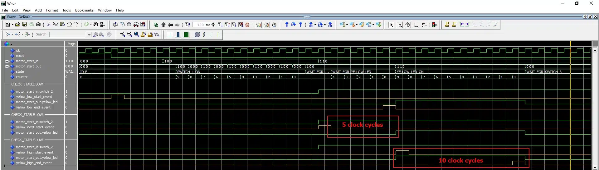
Note: start_event and end_event signals for check_stable are inclusive in the window, and the monitored signal[s] are referenced when start_event='1'.
In this test case, we took the checking operations out of the test case but controlled them from the test case. Also, notice that we didn’t check for RED_LED functionality.
Driver within the test case and self-checking checker
One drawback of the previous approach is that it’s less readable. The test case contains information that’s not interesting or related to the test nor the functionality, such as the start_event and end_event signals. We want to hide all these details, have only the driver in the test case, and make a self-checking checker.
Let’s start by designing the driver.
VHDL’s procedures are a good candidate for that. If you don’t know how to use a VHDL procedure, check out this tutorial.
Below is the procedure switch_driver from motor_tb_pkg.
PROCEDURE switch_driver(
  SIGNAL switches     : OUT MOTOR_START_IN_RECORD_TYPE;
  CONSTANT clk_period : IN TIME;
  CONSTANT sw1_delay  : IN INTEGER;
  CONSTANT sw2_delay  : IN INTEGER;
  CONSTANT sw3_delay  : IN INTEGER) IS
BEGIN
  IF (sw1_delay = 0) THEN
    WAIT FOR clk_period * sw1_delay;
    switches.switch_1 <= '1';
  ELSIF (sw1_delay = -1) THEN
    switches.switch_1 <= '0';
  END IF;
  IF (sw2_delay = 0) THEN
    WAIT FOR clk_period * sw2_delay;
    switches.switch_2 <= '1';
  ELSIF (sw2_delay = -1) THEN
    switches.switch_2 <= '0';
  END IF;
  IF (sw3_delay = 0) THEN
    WAIT FOR clk_period * sw3_delay;
    switches.switch_3 <= '1';
  ELSIF (sw3_delay = -1) THEN
    switches.switch_3 <= '0';
  END IF;
END PROCEDURE switch_driver;
We provide the clock period for calculating the delays and an integer that specifies the desired delay for each switch in clock periods.
- Natural values (>=0) means: turn on the switch after (
clk_period*sw_delay). - The value -1 means: turn the switch off.
- All other negative values means: do nothing.
Now we can use this procedure inside the test case as follows:
switch_driver(motor_start_in,C_CLK_PERIOD,3,12,20);
This will turn switch_1 on after 3 clock cycles and then turn switch_2 on after 12 clock cycles and, and finally, turn switch_3 on after 20 clock cycles.
So far, we have been using VUnit’s default checker. VUnit provides the possibility to have a custom checker. This is useful when you have a big test case with a lot of checking, and you want to have statistics about the checking, or you don’t want to get the checking mixed up with the rest of the testbench.
We will create a custom checker for RED_LED and set the failing log level to WARNING:
CONSTANT RED_CHECKER : checker_t := new_checker("red_led_checker", WARNING);
And we enable logging passing checks for RED_CHECKER in the Setup VUnit section:
show(get_logger(RED_CHECKER), display_handler, pass);
Now let us move to the self-checking checker (or monitor). We will design a self-checking checker for RED_LED first, and we will use a process for this as follows:
- Wait for switch_1 to be turned ON and add a
start_eventfor all LEDs low:
red_monitor_process : PROCESS
BEGIN
  WAIT UNTIL reset = '0';
  pulse_high(clk, led_low_start_event);
  WAIT UNTIL motor_start_in.switch_1 = '1';
- We use the same FOR LOOP from the first test case for RED_LED blinking and add a
start_eventfor RED_LED high:
-- RED_LED is blinking
FOR i IN 0 TO 4 LOOP
  IF (motor_start_in.switch_1 = '1' AND
      motor_start_in.switch_2 = '0' AND
      motor_start_in.switch_3 = '0') THEN

    WAIT UNTIL rising_edge(clk);
    WAIT FOR 1 ps;
    check(RED_CHECKER, motor_start_out.red_led = '1',
          result("for red_led blink high"));

    WAIT UNTIL rising_edge(clk);
    WAIT FOR 1 ps;
    check(RED_CHECKER, motor_start_out.red_led = '0',
          result("for red_led blink low"));

    -- RED_LED is constantly lighting start event
    IF (i = 4) THEN -- finish blinking
      WAIT UNTIL rising_edge(clk);
      WAIT FOR 1 ps;
      check(RED_CHECKER, motor_start_out.red_led = '1',
            result("for red_led blink low"));
      pulse_high(clk, red_high_start_event);
    END IF;
  ELSE
  -- perform check for error (All led high until all switches are off)
  END IF;
END LOOP;
- Now we wait for switch_2 to be turned ON, and then we add an
end_eventfor RED_LED high:
  IF (motor_start_in.switch_2 /= '1') THEN
    WAIT UNTIL motor_start_in.switch_2 = '1';
  END IF;
  WAIT UNTIL rising_edge(clk);
  WAIT FOR C_CLK_PERIOD * 14;
  -- RED_LED is constantly lighting end event
  pulse_high(clk, red_high_end_event);
END PROCESS red_monitor_process;
- Now we add the
check_stableprocedures for RED_LED high and low:
-- check that RED_LED is low from start until switch_1 is ON
-- Note the use of motor_start_in.switch_1 as end_event
check_stable(RED_CHECKER, clk, enable, led_low_start_event,
             motor_start_in.switch_1, motor_start_out.red_led,
             result("RED_LED low before switch_1"));

-- check that RED_LED is low after switch_2 is ON
check_stable(RED_CHECKER, clk, enable, red_high_start_event,
             red_high_end_event, motor_start_out.red_led,
             result("RED_LED high after switch_1"));
Let’s test this with the following test case:
ELSIF run("red_led_output_self-check") THEN
  info("---------------------------------------------------------------");
  info("TEST CASE: red_led_output_self-check");
  info("---------------------------------------------------------------");
  WAIT UNTIL reset = '0';
  -- turn switch_1 on after 3 clk cycles and switch_2 after 13 clk cycles
  switch_driver(motor_start_in,C_CLK_PERIOD,3,13,-1);

  WAIT FOR C_CLK_PERIOD * 3; -- dummy wait
  info("===== TEST CASE FINISHED =====");
We run the simulation like this:
python .\run.py *red_led* -v
The result will be:

Note that the checker is now red_led_checker.
We can follow the same approach to design a self-checking checker for YELLOW_LED, but I will leave this as an exercise for the reader. However, I will show the next different ways to verify the GREEN_LED functionality using check, check_stable, check_next, and check_equal procedures.
To verify that GREEN_LED is OFF from the beginning until the first time switch_3 is turned ON, we simply use the check_stable procedure:
-- check that GREEN_LED is low from start until switch_3 is ON.
check_stable(clk, enable, led_low_start_event,
             motor_start_in.switch_3, motor_start_out.green_led,
             result("GREEN_LED low before switch_3"));
One way to verify that GREEN_LED is ON when switch_3 is turned ON is using the check_next procedure. We call it with switch_3 as the start_event, assign 1 clock cycle to num_cks, and allow overlapping:
-- check that GREEN_LED is high using check_next
check_next(clock       => clk,
           en          => green_next_en,
           start_event => motor_start_in.switch_3,
           expr        => motor_start_out.green_led,
           msg         => result("for green_led high using check_next"),
           num_cks     => 1,
           allow_overlapping   => true,
           allow_missing_start => false);
Because we allowed overlapping, this procedure will be triggered on every rising edge of the clock when switch_3 is ‘1’.t will expect that GREEN_LED is ‘1’ after one clock cycle, and this is what we want.
Another way to test the GREEN_LED functionality is using the clocked version of the check procedure with a delayed version of switch_3 as Enable for this procedure:
switch_3_delayed <= motor_start_in.switch_3'delayed(C_CLK_PERIOD + 1 ps)
                    AND NOT enable;
check(clock => clk,
      en    => switch_3_delayed,
      expr  => motor_start_out.green_led,
      msg   => result("for green_led high using delayed"));
switch_3_delayed is a 1 clock cycle delayed signal of switch_3. Thus it will enable this procedure always 1 clock cycle after switch_3 is ‘1’, and the procedure check that GREEN_LED is ‘1’ when it is enabled.
The switch_3_delayed signal is a delayed version switch_3 by one clock cycle. Thus it will enable this procedure always one clock cycle after switch_3 is ‘1’. When enabled, the procedure checks that GREEN_LED is ‘1’.
Note: the AND NOT enable in switch_3_delayed is just to mask this signal when we are not using the process approach.
Finally, we can use a dedicated process with a VHDL While loop to perform the checking for GREEN_LED:
green_monitor_process : PROCESS
BEGIN
  WAIT UNTIL enable = '1' AND
             motor_start_in.switch_1 = '1' AND
             motor_start_in.switch_2 = '1' AND
             motor_start_in.switch_3 = '1';
  WHILE motor_start_in.switch_3 = '1' LOOP
    WAIT UNTIL rising_edge(clk);
    WAIT FOR 1 ps;
    check_equal(led_out, STD_LOGIC_VECTOR'("100"),
                result("for led_out when switch_3 on"));
  END LOOP;
END PROCESS green_monitor_process;
Now we develop a test case for GREEN_LED as follows:
ELSIF run("switch_3_on_output_check") THEN
  info("-------------------------------------------------------------");
  info("TEST CASE: switch_3_on_output_check");
  info("-------------------------------------------------------------");
  info("check using a clocked check PROCEDURES");
  WAIT UNTIL reset = '0';
  switch_driver(motor_start_in,C_CLK_PERIOD,3,12,20);
  WAIT FOR C_CLK_PERIOD * 5;
  switch_driver(motor_start_in,C_CLK_PERIOD,-2,-2,-1);
  WAIT FOR C_CLK_PERIOD * 3; -- dummy wait
  info("-------------------------------------------------------------");

  info("check using check_next PROCEDURES");
  green_next_en <= '1';
  switch_driver(motor_start_in,C_CLK_PERIOD,-2,-2,10);
  WAIT FOR C_CLK_PERIOD * 5;
  switch_driver(motor_start_in,C_CLK_PERIOD,-2,-2,-1);
  WAIT FOR C_CLK_PERIOD * 3; -- dummy wait
  green_next_en <= '0';
  info("-------------------------------------------------------------");

  info("check using check_equal process");
  enable <= '1';
  switch_driver(motor_start_in,C_CLK_PERIOD,-2,-2,10);
  WAIT FOR C_CLK_PERIOD * 5;
  switch_driver(motor_start_in,C_CLK_PERIOD,-2,-2,-1);
  WAIT FOR C_CLK_PERIOD * 10; -- dummy wait
  info("===== TEST CASE FINISHED =====");
After writing the test case, you can run it and check the different results.
We can see that the test cases in the self-checking approach are much more readable, even for engineers without knowledge in VHDL.
There are other test cases in the testbench file. We can start them using this command:
python .\run.py *motor_start_tb* --list
And this is the output printed to the console:
tb_lib.motor_start_tb.switches_off_output_check
tb_lib.motor_start_tb.switch_1_on_output_check
tb_lib.motor_start_tb.switch_2_on_output_check
tb_lib.motor_start_tb.red_led_output_self-check
tb_lib.motor_start_tb.switch_3_on_output_check
tb_lib.motor_start_tb.switch_2_error_output_check
Listed 6 tests
We can run all test cases by typing:
python .\run.py
And the result is as follows:
==== Summary =============================================================
pass tb_lib.motor_start_tb.switch_1_on_output_check    (0.4 seconds)
pass tb_lib.motor_start_tb.switch_2_on_output_check    (0.4 seconds)
pass tb_lib.motor_start_tb.red_led_output_self-check   (0.4 seconds)
pass tb_lib.motor_start_tb.switch_3_on_output_check    (0.4 seconds)
fail tb_lib.motor_start_tb.switches_off_output_check   (0.9 seconds)
fail tb_lib.motor_start_tb.switch_2_error_output_check (0.4 seconds)
==========================================================================
pass 4 of 6
fail 2 of 6
==========================================================================
Total time was 2.9 seconds
Elapsed time was 2.9 seconds
==========================================================================
Some failed!
Summary
The VUnit framework provides advanced features for test running automation and rich libraries for testbenches development. In addition, it enables design engineers to test their design early and often.
VUnit also helps verification engineers developing and running testbenches faster and easier. Most importantly, it has a quick and light learning curve.
Where to go from here
* Update
Check out VHDLwhiz's new VUnit course with 15 video lessons!
Course: VUnit for structured testbench and advanced BFM design
Other useful links:
Download the example project by using the form below!


In order to install vunit package directly without a need to download its source code, you can take advantage of pip:
pip install vunit_hdl
Release 4.5.0 has just been released.
Thanks, Luca! That’s a great tip.
Sorry for the typo. The command should be:
pip install vunit-hdl
Please refer to https://pypi.org/project/vunit-hdl/4.5.0/
First, congrats in this blog and this article. I am new user of VUNIT and I have a question regarding how to run vunit with the GUI. It is a requirement in the organization that I work for that I have to have the waveforms. I have multiple tb_* with multiple cases in each one.
When I run run.py -g and then in Modelsim vunit_run, Modelsim only execute the first test case and then stops the execution with the message “Break in Subprogram stop at …/Python/Python39/Lib/site-packages/vunit/vhdl/core/src/stop_body_2008p.vhd line 13”
I need to execute all together instead of individual test cases becase some test cases requires the previous one to be executed first.
Is there any way that I can execute all test cases with the GUI?
Regards,
Victor
add:
— vunit: run_all_in_same_sim
at the top of your testbench.
I have some doubts with using multiple tools.
I use libero, questa for running simulations with modelsim for different applications.
Any way to be able to use Vunit with multiple tools?
Prior to Vunit – i used to give the tool folder path along with vsim or vcom commands. But with vunit this seems not possible.
Please help if any solution
Hello Ahmad and Team,
Thank you for such a descriptive and informative blog on Vunit. I have one comment and one question.
Comment:
Doesnt the line 8, 14, and 20 of your switch driver procedure be
instead of
to accept delay value 0 and greater?
Question:
I assume we can integrate other verification libraries like OSVVM in our code mainly to integrate their Buss Functional Models like that for AXI-lite, AXIFULL, AXIStream, UART etc
or does Vunit has its own BFMs to verify Buss interfaces and peripherals like UART, SPI and I2C?
Thank you