Creating modules is a great way to reuse code, but often you need the same module with smaller variations throughout your design. This is what generics and the generic map are for. It allows you to make certain parts of the module configurable at compile-time.
Constants are used when we want to avoid typing the same value over and over again. They can be used for defining bit-widths of signal vectors at compile-time, and they can even be mapped to generic constants as well. Constants can be used in place of signals and variables anywhere in the code, but their values cannot be changed after compile-time.
This blog post is part of the Basic VHDL Tutorials series.
In the previous tutorial, we created a 4-input multiplexer module with a bus width of 8 bits. But what if we also need a similar MUX with a different bus width? Is the only solution to copy-paste the code into a new module, and change the numbers?
Fortunately, no.
It is possible to create constants in VHDL using this syntax:
constant <constant_name> : <type> := <value>;
Constants can be declared along with signals in the declarative part of a VHDL file, or they can be declared along with variables in a process.
Constants can be passed into a module through the entity by using the generic keyword. The syntax for creating an entity for a module which accepts generic constants is:
entity <entity_name> is
 generic(
     <entity_constant_name> : <type> [:= default_value];
     ...
 );
 port(
     <entity_signal_name> : in|out|inout <type>;
     ...
 );
 end entity;
The syntax for instantiating a generic module in another VHDL file is:
<label> : entity <library_name>.<entity_name>(<architecture_name>)
 generic map(
     <entity_constant_name> => <value_or_constant>,
     ...
 )
 port map(
     <entity_signal_name> => <local_signal_name>,
     ...
 );
Exercise
In this video tutorial, we will learn how to create and instantiate a module with generic constants in VHDL:
The final code for the generic MUX testbench:
library ieee;
use ieee.std_logic_1164.all;
use ieee.numeric_std.all;

entity T16_GenericMapTb is
end entity;

architecture sim of T16_GenericMapTb is

    constant DataWidth : integer := 8;

    signal Sig1 : signed(DataWidth-1 downto 0) := x"AA";
    signal Sig2 : signed(DataWidth-1 downto 0) := x"BB";
    signal Sig3 : signed(DataWidth-1 downto 0) := x"CC";
    signal Sig4 : signed(DataWidth-1 downto 0) := x"DD";

    signal Sel : signed(1 downto 0) := (others => '0');

    signal Output : signed(DataWidth-1 downto 0);

begin

    -- An Instance of T16_GenericMux with architecture rtl
    i_Mux1 : entity work.T16_GenericMux(rtl)
    generic map(DataWidth => DataWidth)
    port map(
        Sel    => Sel,
        Sig1   => Sig1,
        Sig2   => Sig2,
        Sig3   => Sig3,
        Sig4   => Sig4,
        Output => Output);

    -- Testbench process
    process is
    begin
        wait for 10 ns;
        Sel <= Sel + 1;
        wait for 10 ns;
        Sel <= Sel + 1;
        wait for 10 ns;
        Sel <= Sel + 1;
        wait for 10 ns;
        Sel <= Sel + 1;
        wait for 10 ns;
        Sel <= "UU";
        wait;
    end process;

end architecture;
The final code for the generic MUX module:
library ieee;
use ieee.std_logic_1164.all;
use ieee.numeric_std.all;

entity T16_GenericMux is
generic(DataWidth : integer);
port(
    -- Inputs
    Sig1 : in signed(DataWidth-1 downto 0);
    Sig2 : in signed(DataWidth-1 downto 0);
    Sig3 : in signed(DataWidth-1 downto 0);
    Sig4 : in signed(DataWidth-1 downto 0);

    Sel  : in signed(1 downto 0);

    -- Outputs
    Output : out signed(DataWidth-1 downto 0));
end entity;

architecture rtl of T16_GenericMux is
begin

    process(Sel, Sig1, Sig2, Sig3, Sig4) is
    begin

        case Sel is
            when "00" =>
                Output <= Sig1;
            when "01" =>
                Output <= Sig2;
            when "10" =>
                Output <= Sig3;
            when "11" =>
                Output <= Sig4;
            when others => -- 'U', 'X', '-', etc.
                Output <= (others => 'X');
        end case;

    end process;

end architecture;
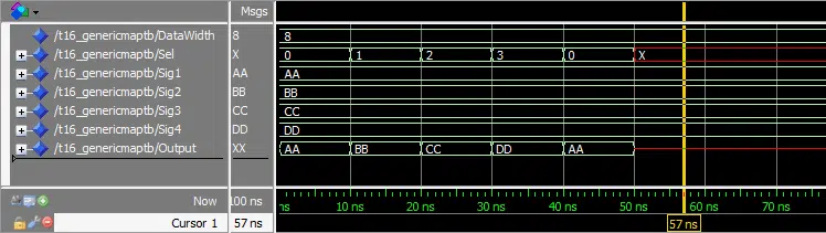
The waveform window in ModelSim after we pressed run and zoomed in on the timeline:
Need the Questa/ModelSim project files?
Let me send you a Zip with everything you need to get started in 30 seconds
Tested on Windows and Linux Loading Gif.. 
Analysis
We created a MUX module with a configurable bus width. Now, the bus width is specified in only one place, in the testbench file. We can easily change it to create a MUX with a different bus width.
If we compare the waveform to the one from the previous tutorial, we can see that the behavior is identical. This is because we haven’t changed the behavior of the code at all.
Get free access to the Basic VHDL Course
Download the course material and get started.
You will receive a Zip with exercises for the 23 video lessons as VHDL files where you fill in the blanks, code answers, and a link to the course.
By submitting, you consent to receive marketing emails from VHDLwhiz (unsubscribe anytime).
Takeaway
- Constants can be used to avoid hard-coding values in multiple places
- Generics can be used to make modules more adaptable


How does the Initialization ( in Testbench line 12-15) work if one changes the data width to 16?
That wouldn’t compile because
x"AA"is of fixed length. You would have to increase tox"AAAA"or do something different like:This would initialize the 16-bit vector to
0x00AA.Great tutorial series! I actually jumped in the deep end with a FPGA project.. I make some good progress (without knowing how to simulate). Now going to to basics to learn to simulate!. Your an awesome teacher!!!!!
One question.. In the above example I define the DataWidth in the test bench as follows:
constant DataWidth : integer := 8;
But say I want to run my project on a real FPGA (after setting up the chip, pin planning etc), would I need to then have another “constant DataWidth : integer := 8;” in the rtl file also only when im testing in real life, and then deleting it when I run simulation again? Is there a better way to set this up? Maybe define a “simulation” constant in the Tb and when the code is running on a real device it checks the if “simulation” constant is not present and then default to “run mode” values..
Any tips would be neat!
Hi Dave,
That’s a great question! I see you have stumbled upon a problem that many VHDL engineers before you have struggled with. There are several ways to handle this.
You can give the generic a default value like this:
If you don’t assign anything to this generic when instantiating the module, the default value is chosen. You can use this method to give an implementation value to a constant with the option to override it in the testbench.
Another option is to give the generic a value in the synthesis tool. All synthesis tools have the option to provide values to generics on the top module. For example, through the Settings → General → Generics/Parameters menu in Xilinx Vivado.
If the generic you want to override isn’t on the top module, but in an instance deeper in the design hierarchy, you can keep the constants in different packages instead of as generics. Include one package in your synthesis project and the other one for the simulation project.
Jonas,
Thanks for that, seems logical 🙂
So in that case is it safe to say that if you which to override a constant in your Tb you should always put them under “generic(..” in your rtl. Also any other constants you which to define in rtl can be put under ‘architecture’. I guess it would be good practice to put ALL constants under ‘generic’ as you will probably need to override them one day!
Another question on this topic.. Since we can override ‘generics’ and ‘ports’, how would we control signals/wires in rtl from Tb that are not connected to any external pins? Can you just define it under ports but not ‘pin planner’ them?
Assigning default values to generics can only be used on the top module if the goal is to differentiate between synthesis and simulation constants. Of course, you can propagate generic values from the top level to submodules if this is practical for you.
The generic override I use the most is for the clock frequency. Whenever my RTL code has to know the clock frequency, I declare it as a generic constant with the true clock frequency as the default value:
entity top is
  generic (
    clk_hz : integer := 100e6
  );
...
end top;
The problem is that the high clock frequency makes the simulation really slow. To simulate one second, you would have to sit through 200 million events on the clock signal for a design running on 100 MHz. To circumvent this problem, I usually assign a much lower value to the clock frequency generic in the testbench:
  DUT : entity work.top(rtl)
  generic map (
    clk_hz => 100
  )
...
The default value is chosen by the synthesis tool, while your simulation completes almost instantly.
You can access signals inside of submodules from the testbench by using “hierarchical signal access”. I don’t have a blog post covering this yet. You will have to google the term. It’s simple enough though, just use this syntax to reach within your hierarchy:
The dot separates each module level. Add another dot (my_dut.my_submodule.my_sig) to reach deeper into the hierarchy. Note that this only works in VHDL-2008 and beyond. This shouldn’t be a problem because most people use 2008 for their testbenches by now, even if the RTL modules require VHDL-93.
Jonas,
I sent a reply but didnt show up. So here goes the simpler version!
I followed your above clk_hz instructions and that did compile. However, when I tried to access the value like this:
.. I get a compilation error. So looks like there is a trick to access the data.
Also “hierarchical signal access” seems to be a pain to work with. I then realized (correct me if im wrong) that its good practice to only communicate with signals in your module via in/out ports. Trying to R/W to signals at hierarchical level (in your Tb) turns out to be messy and hard to test.
I still have many questions, so where is the best place to post ideas for future tutorials?
This is an answer to your latest reply to this thread. The blog doesn’t support three levels of replies. ?
Strange that you were unable to get the report statement working, I was able to compile and run the line that you had problems with in ModelSim:
This was printed to the ModelSim console:
Perhaps you have placed the report statement somewhere it’s not allowed? I put it within a process, then it works.
I usually define the hierarchical signals as an alias in the declarative region of the process. Then you can use the alias within the process without cluttering the code with the ugly long paths:
process
    alias my_sig is << signal DUT.my_sig : integer >>;
begin

  wait on my_sig;
  report "my_sig = " & integer'image(my_sig);

end process;
This is an example printout from the code above:
You are right that relying too much on hierarchical signal access can make your testbench code messy. However, I don’t have any strict rules for when to use them and when to split up the module. It’s a tradeoff between having self-contained modules and having a well-structured testbench.
When using hierarchical signal access, you are, in my opinion, engaging in white-box testing. You are assuming knowledge of the inner workings of the module. Thus, you cannot replace the module with another implementation and still use the same testbench. There’s no right or wrong. It’s just something to think about if you want to do white-box or black-box testing.
Feel free to join the discussion and ask questions in my private VHDL for FPGA Engineers Facebook group!
generic constants can have default values, this way the module instantiating this module need not give a value for the generic constant.Please update your example to show this feature of VHDL.
Yes, I’ve updated the syntax description with a
[:= default_value];option.The constant will get the default value if an assignment to that particular generic isn’t present when instantiating the module. Furthermore, any assigned value will override the default.
I often use default values on generics to speed up the simulation. For example, if the device under test (DUT) needs to know the clock frequency to measure real-time. Then I will set the
clk_czgeneric constant to the real clock frequency:entity dut is generic ( -- The system clock is 100 MHz clk_hz : positive := 100e3 ); port ( clk : in std_logic; rst : in std_logic; ... ); end dut;But in the testbench, I will override
clk_hzwith a much lower clock frequency to substantially cut simulation time:I have a generic of std_logic_vector of 40 size in vhdl design file. I am trying to override this generic in verilog. Any suggestions on how this can be done? If I can override using command line then please give the command with the example.
You can give a default value to the generic in the VHDL code:
library ieee;
use ieee.std_logic_1164.all;
use ieee.numeric_std.all;

entity my_module is
  generic (data_width : integer := 32); -- Defaults to 32
  port (
    sig_in : std_logic_vector(data_width - 1 downto 0);
    sig_out : std_logic_vector(data_width - 1 downto 0)
  );
end my_module;

architecture rtl of my_module is
begin
end architecture;
Or if you can’t touch the original VHDL module, create a wrapper in VHDL and import that one in your Verilog project instead:
entity my_module_wapper is
  port (
    sig_in : std_logic_vector(31 downto 0);
    sig_out : std_logic_vector(31 downto 0)
  );
end my_module_wapper;

architecture rtl of my_module_wapper is
begin

  MY_MODULE : entity work.my_module(rtl)
  generic map (data_width => 32)
  port map (
    sig_in => sig_in,
    sig_out => sig_out
  );

end architecture;