A module is a self-contained unit of VHDL code. Modules communicate with the outside world through the entity. Port map is the part of the module instantiation where you declare which local signals the module’s inputs and outputs shall be connected to.
In previous tutorials in this series we have been writing all our code in the main VHDL file, but normally we wouldn’t do that. We create logic with the purpose of using it in an FPGA or ASIC design, not for the simulator.
A VHDL module created for running in a simulator usually has no input or output signals. It is entirely self-contained. That’s why the entity of our designs have been empty. There has been nothing between the entity tag and the end entity; tag.
This blog post is part of the Basic VHDL Tutorials series.
A module without any input or output signals cannot be used in a real design. Its only purpose is to allow us to run VHDL code in a simulator. Therefore it is referred to as a testbench. To simulate a module with input and output signals we have to instantiate it in a testbench.
Modules and testbenches often come in pairs, and they are stored in different files. A common naming scheme is to call the testbench the module name with “Tb” appended, and to name the architecture “sim”. If the module is called “MyModule” the testbench will be called “MyModuleTb”. Consequently, the filenames become “MyModuleTb.vhd” and “MyModule.vhd”.

With the help of the testbench code we can verify that the module is working correctly in a simulation environment. The module being tested is commonly referred to a the device under test (DUT).
Modules can also be instantiated within other modules. Partitioning the code into modules allows it to be instantiated multiple times. You can create several instances of a module within the same design, and it can be reused across many designs.
The syntax for an entity with a port in VHDL is:
entity <entity_name> is
 port(
     <entity_signal_name> : in|out|inout <signal_type>;
     ...
 );
 end entity;
The syntax for instantiating such a module in another VHDL file is:
<label> : entity <library_name>.<entity_name>(<architecture_name>) port map(
     <entity_signal_name> => <local_signal_name>,
     ...
 );
The <label> can be any name, and it will show up in the hierarchy window in ModelSim. The <library_name> for a module is set in the simulator, not in the VHDL code. By default every module is compiled into the work library. The <entity_name> and <architecture_name> must match the module we are creating an instance of. Finally, each of the entity signals must be mapped to a local signal name.
There are other ways to instantiate a module in VHDL, but this is the basic syntax for explicit instantiation.
Exercise
In this video tutorial we will learn how to create and instantiate a module in VHDL:
The final code for the MUX testbench:
library ieee;
use ieee.std_logic_1164.all;
use ieee.numeric_std.all;

entity T15_PortMapTb is
end entity;

architecture sim of T15_PortMapTb is

    signal Sig1 : unsigned(7 downto 0) := x"AA";
    signal Sig2 : unsigned(7 downto 0) := x"BB";
    signal Sig3 : unsigned(7 downto 0) := x"CC";
    signal Sig4 : unsigned(7 downto 0) := x"DD";

    signal Sel : unsigned(1 downto 0) := (others => '0');

    signal Output : unsigned(7 downto 0);

begin

    -- An instance of T15_Mux with architecture rtl
    i_Mux1 : entity work.T15_Mux(rtl) port map(
        Sel    => Sel,
        Sig1   => Sig1,
        Sig2   => Sig2,
        Sig3   => Sig3,
        Sig4   => Sig4,
        Output => Output);

    -- Testbench process
    process is
    begin
        wait for 10 ns;
        Sel <= Sel + 1;
        wait for 10 ns;
        Sel <= Sel + 1;
        wait for 10 ns;
        Sel <= Sel + 1;
        wait for 10 ns;
        Sel <= Sel + 1;
        wait for 10 ns;
        Sel <= "UU";
        wait;
    end process;

end architecture;
The final code for the MUX module:
library ieee;
use ieee.std_logic_1164.all;
use ieee.numeric_std.all;

entity T15_Mux is
port(
    -- Inputs
    Sig1 : in unsigned(7 downto 0);
    Sig2 : in unsigned(7 downto 0);
    Sig3 : in unsigned(7 downto 0);
    Sig4 : in unsigned(7 downto 0);

    Sel  : in unsigned(1 downto 0);

    -- Outputs
    Output : out unsigned(7 downto 0));
end entity;

architecture rtl of T15_Mux is
begin

    process(Sel, Sig1, Sig2, Sig3, Sig4) is
    begin

        case Sel is
            when "00" =>
                Output <= Sig1;
            when "01" =>
                Output <= Sig2;
            when "10" =>
                Output <= Sig3;
            when "11" =>
                Output <= Sig4;
            when others => -- 'U', 'X', '-', etc.
                Output <= (others => 'X');
        end case;

    end process;

end architecture;
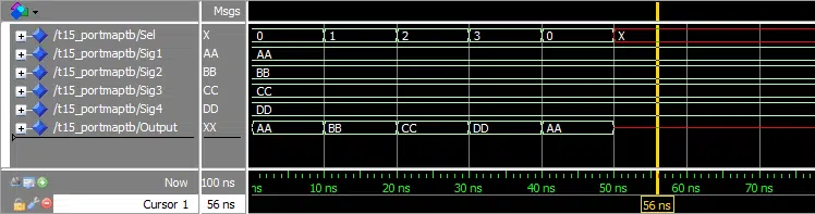
The waveform window in ModelSim after we pressed run and zoomed in on the timeline:
Need the Questa/ModelSim project files?
Let me send you a Zip with everything you need to get started in 30 seconds
Tested on Windows and Linux Loading Gif.. 
Analysis
As we can see from the waveform, the multiplexer (MUX) module works as expected. The waveform is identical to the one from the previous tutorial which we created without using modules.
Now there is a clear separation between the design module and the testbench. The module containing the MUX is what we intend to use in a design, and the testbench’s only purpose is to allow us to run it in a simulator. There is a process in the testbench that uses wait statements for creating artificial time delays in the simulation. The design module has no notion of time, it only reacts to external stimuli.
We named the architecture of the testbench sim, for simulation. The architecture of the design module was named rtl, which stands for register-transfer level. These are just naming conventions. When you see a file with such a name, you immediately know whether it’s a testbench or a design module. Different companies may have different naming conventions.
Get free access to the Basic VHDL Course
Download the course material and get started.
You will receive a Zip with exercises for the 23 video lessons as VHDL files where you fill in the blanks, code answers, and a link to the course.
By submitting, you consent to receive marketing emails from VHDLwhiz (unsubscribe anytime).
Takeaway
- Input and output signals are specified in the entity of a module
- A module with no in/out signals is called a testbench, and it can only be used in a simulator
- A module with in/out signals can usually not be run directly in a simulator


Thank you for the tutorial Jonas!
Can you comment on when VHDL component’s should be used rather than instantiating entities directly from their libraries?
The entity instantiation method was introduced in VHDL-93. For most cases, this made the component instantiation method obsolete. However, there is one circumstance which still requires using the component method.
That’s when instantiating black-box modules in your design. A black-box module doesn’t have any VHDL code or implementation. Therefore, you must tell the synthesis tool what the components entity declaration looks like. You can do that by declaring the component.
Typically, you would need to do this if you’ve bought a module as a pre-routed netlist, rather than as VHDL code. You basically tell the synthesis tool that there will a module here with a certain kind of interface, and don’t be bothered by the missing implementation. Finally, in the place and route phase, the netlist of the black-box module is swapped in to take the place of the empty component.