Reading signal values from file is an alternative way of generating stimuli for the device on test (DUT). The testbench sequence and timing is hard-coded in a stimulus file that is read by the VHDL testbench, line by line. This allows you to easily change the pattern of the waveform that you want to feed to the test object.
Sometimes you have a very specific test pattern or sequence of events that you want to put your DUT through. You can achieve this by specifying in an ASCII file the signal values that each signal should have, as well as the relative simulation time they should change on. The role of the VHDL testbench in such a strategy is to read the data from the stimulus file and apply the values to the DUT inputs at the correct time.
This article is the second one in a series about file access in VHDL. We looked at how to read hexadecimal, octal, and binary values from file in the previous blog post, go back and read it if you want to know more about reading from file using the TEXTIO library in VHDL.
This blog post is part of a series about using the TEXTIO library in VHDL. Read the other articles here:
How to initialize RAM from file using TEXTIO
BMP file bitmap image read using TEXTIO
The test case
The example DUT will be a 4-input multiplexer (MUX) taken from one of my earlier blog posts. It’s a standard, asynchronous 4-to-1 MUX with a data width of one byte. How it works isn’t important for this article because we’re not going to do any checking of the outputs, it’s just for demonstration purposes.
The entity of the MUX is shown below.
entity mux_4 is
  port(
    -- Data in
    din_0 : in unsigned(7 downto 0);
    din_1 : in unsigned(7 downto 0);
    din_2 : in unsigned(7 downto 0);
    din_3 : in unsigned(7 downto 0);

    -- Selector
    sel  : in unsigned(1 downto 0);

    -- Data out
    dout : out unsigned(7 downto 0));
end entity;
After importing the necessary packages at the top of the VHDL file, we go on to declare the input signals that we are going to connect to the DUT. As you can see from the listing below, they are blueprints from the MUX entity declaration.
signal din_0 : unsigned(7 downto 0);
signal din_1 : unsigned(7 downto 0);
signal din_2 : unsigned(7 downto 0);
signal din_3 : unsigned(7 downto 0);
signal sel  : unsigned(1 downto 0);
signal dout : unsigned(7 downto 0);
We use the entity instantiation method to create an instance of the MUX with the label “DUT” at the top of the architecture region of our testbench. The entity signals are connected to the local testbench signals with the same names, as shown in the code below.
DUT: entity work.mux_4(rtl)
port map (
    din_0 => din_0,
    din_1 => din_1,
    din_2 => din_2,
    din_3 => din_3,
    sel  => sel,
    dout => dout
);
The stimulus file
A stimulus file can have a lot of different formats, the one presented here is just an example that I came up with from the top of my head while writing this article. Nevertheless, when you understand how I created it you should be able to modify it to suit your needs.
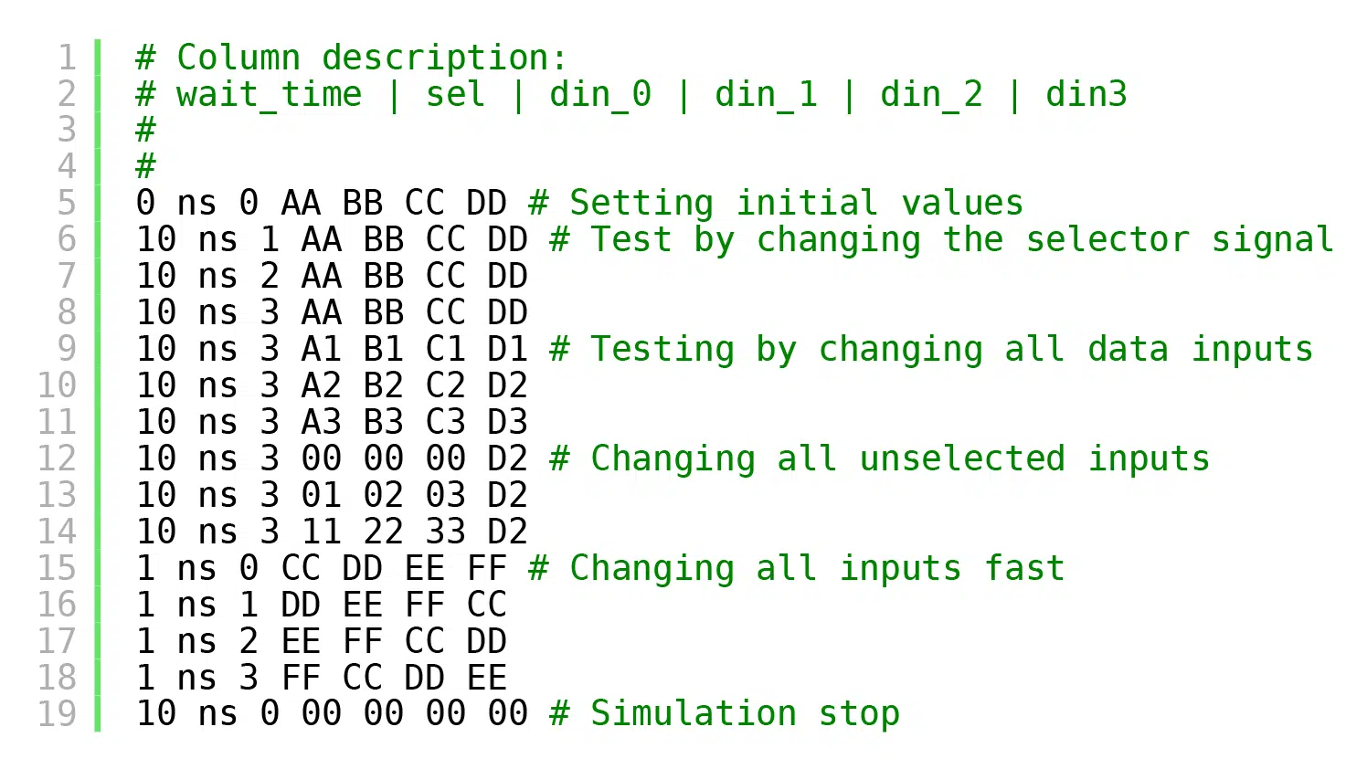
The listing below shows the complete stimulus file used in this example.
# Column description:
# wait_time | sel | din_0 | din_1 | din_2 | din3 # Optional console printout

0 ns 0 AA BB CC DD # Setting initial values
10 ns 1 AA BB CC DD # Testing by changing the selector signal
10 ns 2 AA BB CC DD
10 ns 3 AA BB CC DD
10 ns 3 A1 B1 C1 D1 # Testing by changing all data inputs
10 ns 3 A2 B2 C2 D2
10 ns 3 A3 B3 C3 D3
10 ns 3 00 00 00 D2 # Changing all unselected inputs
10 ns 3 01 02 03 D2
10 ns 3 11 22 33 D2
1 ns 0 CC DD EE FF # Changing all inputs fast
1 ns 1 DD EE FF CC
1 ns 2 EE FF CC DD
1 ns 3 FF CC DD EE
10 ns 0 00 00 00 00 # Simulation stop
Let’s ignore the comments for now, those are the ones marked in green, always starting with a ‘#’ character. Each line represents one timestep in the simulation. There are six columns of commands on each line, actually seven columns of text, but the first two columns belong to the same data item.
Text columns one and two describe a time value, for how long the simulator should pause on that line before applying the values that are listed in the other columns. Thus, the absolute simulation time when the command is executed is relative to the event described by the previous line. We are using only 0, 1, or 10 nanoseconds, but it could be anything, 1000 nanoseconds or 1000 hours (1000 hr) for that matter.
The remaining five text columns describe the signal values to apply to the DUT inputs. They are given as hexadecimal literals and the signal ordering is sel, din_0, din_1, din_2, and finally din_3.
Now, over to the comments. There are two types of comments; single-line comments and trailing comments. They shall be treated differently by our testbench. Single-line comments, like the ones at the top of the file, will be ignored. Trailing comments, on the other hand, shall be printed to the simulator console. We can use them to give us clues about what’s happening while the simulation is running.
Reading the stimulus file in VHDL
VHDL isn’t the greatest language for text processing, but it does the job. The support for dynamic strings is limited, and it’s lacking convenience routines for example for stripping or skipping whitespace. To make it easier on ourselves, we’re going to assume that the stimulus file is nicely written. Let’s take great care to make sure that there is always one space between text elements and a single space between the ‘#’ character and the comment text. Also, no extra leading or trailing spaces anywhere in the stimulus file.
Need the Questa/ModelSim project files?
Let me send you a Zip with everything you need to get started in 30 seconds
Tested on Windows and Linux Loading Gif.. 
PROC_SEQUENCER : process
  file text_file : text open read_mode is "stimulus.txt";
  variable text_line : line;
  variable ok : boolean;
  variable char : character;
  variable wait_time : time;
  variable selector : sel'subtype;
  variable data : dout'subtype;
begin
The declarative region of the PROC_SEQUENCER procedure is shown above. First, we declare the special file object, a VHDL file handler type. Then, we declare a variable of type line. This is simply an access type to a string, a pointer to a dynamically allocated string object. The ok variable of Boolean type is for checking that the read operations are successful. Finally, we declare the four variables char, wait_time, selector, and data. These variables are for extracting the data from each column from every line of text.
while not endfile(text_file) loop

  readline(text_file, text_line);

  -- Skip empty lines and single-line comments
  if text_line.all'length = 0 or text_line.all(1) = '#' then
    next;
  end if;
In the process body, we go straight into a while-loop that will iterate through every line of text in the stimulus file. The readline procedure assigns a new line of text to the text_line variable on every iteration of this loop. After reading the line, we check if the line is empty or if the first character is ‘#’, in which case we go to the next line immediately by using the next keyword to skip an iteration of the loop. Note that we’re using text_line.all to get access to the string inside of the line object.
read(text_line, wait_time, ok);
assert ok
  report "Read 'wait_time' failed for line: " & text_line.all
  severity failure;

hread(text_line, selector, ok);
assert ok
  report "Read 'sel' failed for line: " & text_line.all
  severity failure;
sel <= selector;

hread(text_line, data, ok);
assert ok
  report "Read 'din_0' failed for line: " & text_line.all
  severity failure;
din_0 <= data;

hread(text_line, data, ok);
assert ok
  report "Read 'din_1' failed for line: " & text_line.all
  severity failure;
din_1 <= data;

hread(text_line, data, ok);
assert ok
  report "Read 'din_2' failed for line: " & text_line.all
  severity failure;
din_2 <= data;

hread(text_line, data, ok);
assert ok
  report "Read 'din_3' failed for line: " & text_line.all
  severity failure;
din_3 <= data;
Next follows a number of reads from the text_line object. The read and hread procedure calls skip leading spaces so that we don’t have to do any dummy reads to move the internal read start position inside of the text_line object. We could have omitted the assert statements, but I want the simulation to stop if a read fails. At least in ModelSim, the simulation doesn’t stop automatically when this happens. We assign each successfully read variable to the relevant DUT signal except for the wait_time variable which doesn’t have a corresponding DUT input.
wait for wait_time;
After assigning the signal values, we wait for the specified time. Hitting the wait-statement causes the scheduled signal values to become effective with the same delta cycle.
    -- Print trailing comment to console, if any
    read(text_line, char, ok); -- Skip expected newline
    read(text_line, char, ok);
    if char = '#' then
      read(text_line, char, ok); -- Skip expected newline
      report text_line.all;
    end if;

  end loop;

  finish;

end process;
Finally, when the program wakes up from the wait-statement, we look for an additional trailing comment on the text_line object. Any comment is printed to the console by using the report statement after we have stripped the ‘#’ character and the following whitespace using dummy reads.
After the last line of text from the stimulus file has been processed, the while-loop terminates. There’s a VHDL-2008 finish keyword at the end of the process which is responsible for stopping the testbench.
The output
The example testbench prints out the text shown below to the simulator console when it’s run in ModelSim. We can see that the comments are the ones from the stimulus file. The time values printed are the accumulated simulation times based on the nanosecond delays that were specified in the stimulus file.
# ** Note: Setting initial values
#    Time: 0 ns  Iteration: 1  Instance: /file_stim_tb
# ** Note: Testing by changing the selector signal
#    Time: 10 ns  Iteration: 0  Instance: /file_stim_tb
# ** Note: Testing by changing all data inputs
#    Time: 40 ns  Iteration: 0  Instance: /file_stim_tb
# ** Note: Changing all unselected inputs
#    Time: 70 ns  Iteration: 0  Instance: /file_stim_tb
# ** Note: Changing all inputs fast
#    Time: 91 ns  Iteration: 0  Instance: /file_stim_tbf
# ** Note: Simulation stop
#    Time: 104 ns  Iteration: 0  Instance: /file_stim_tb
# Break in Process PROC_SEQUENCER at file_stim_tb.vhd line 98
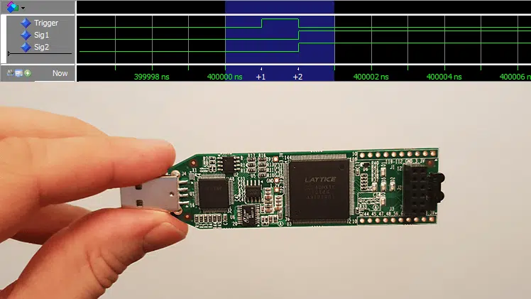
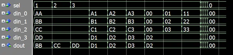
The waveform for the simulation is shown below. It shows a visual representation of how the values from our stimulus file are applied to the signals at the specified simulation times.
Final thoughts
Reading testbench stimuli from file can be advantageous if you have a very specific test pattern that you need to apply. The whole testbench doesn’t have to be controlled by the text file, this example is just meant to show the possibilities of file access in VHDL.
However, one thing we haven’t discussed is checking of the DUT outputs. Our example testbench doesn’t check the outputs at all. You could verify the DUT behavior just as you would have in a full VHDL testbench, for example by using a behavioral model to compare with. Or you could modify the code and stimulus file to include the expected output values. Whichever strategy you choose, make sure that you create a self-checking testbench and don’t rely on manually checking the waveform.
Need the Questa/ModelSim project files?
Let me send you a Zip with everything you need to get started in 30 seconds
Tested on Windows and Linux Loading Gif..