Converting the image file to a bitmap format makes for the easiest way to read a picture using VHDL. Support for the BMP raster graphics image file format is built into the Microsoft Windows operating system. That makes BMP a suitable image format for storing photos for use in VHDL testbenches.
In this article, you will learn how to read a binary image file like BMP and store the data in dynamic memory in the simulator. We will use an example image processing module to convert the image to grayscale, which will be our device under test (DUT). Finally, we write the output from the DUT to a new image that we can compare visually to the original.
This blog post is part of a series about using the TEXTIO library in VHDL. Read the other articles here:
How to initialize RAM from file using TEXTIO
Stimulus file read in testbench using TEXTIO
How about JPG images?
Since I wrote the article you are currently reading, I have published a new course on image processing and testbench design using JPG images. Click the banner below to check it out!
* Update
New VHDL image processing course with 16 video lessons!
Course: Image processing system and testbench design using VHDL
Why bitmap is the best format for VHDL
The most common image file formats on the internet are JPEG and PNG. Both of them use compression. JPEG is lossy, while PNG is lossless. Most formats offer some form of compression because this can dramatically reduce the storage size of the image. While this is fine for normal usage, it’s not ideal for reading in a VHDL testbench.

To be able to process an image in software or hardware, you need to have access to the raw pixel data within your application. You want to have the color and luminance data stored in a matrix of bytes, and this is called bitmap or raster graphics.
Most of the well-known image editors, such as Photoshop or GIMP, are raster-based. They can open a wide range of image formats, but they are all converted to raster graphics internally in the editor.
You can do this in VHDL too, but that would require a considerable coding effort because there aren’t any ready-made solutions for decoding compressed images. A better solution is to convert the test input images to a bitmap format like BMP manually or by incorporating it into the script that launches your testbench.
The BMP image file format
The BMP file format is well documented on Wikipedia. This format has many different variants, but we’ll agree on some specific settings that will make it a lot easier for us. To create our input images, we open them in Microsoft Paint, which comes pre-installed with Windows. Then, we click File→Save as, select Save as type: 24-bit Bitmap (*bmp; *.dib). Name the file something ending with the .bmp suffix and click save.
By making sure that the file is created like this, we can assume that the header is always 54 bytes long BITMAPINFOHEADER variant with pixel format RGB24 mentioned on the Wikipedia page. Furthermore, we’ll only care about a few selected fields within the header. The table below shows the header fields that we are going to read.
| Offset (Dec) | Size (B) | Expected (Hex) | Description |
|---|---|---|---|
| 0 | 2 | “BM” (42 4D) | ID field |
| 10 | 4 | 54 (36 00 00 00) | Pixel array offset |
| 14 | 4 | 40 (28 00 00 00) | Header size |
| 18 | 4 | Read value | Image width in pixels |
| 22 | 4 | Read value | Image height in pixels |
| 26 | 1 | 1 (01) | Number of color planes |
| 28 | 1 | 24 (18) | Number of bits per pixel |
The values marked in green are the only ones we really need to look at because we know which values to expect in the other header fields. If you agreed only to use images of predefined fixed dimensions every time, you could skip the entire header and start reading at byte offset number 54 within the BMP file. That’s where the pixel data will be found.
Nevertheless, we will check that the other listed values are as expected. It’s not difficult to do since we are already reading the header. It also safeguards against user errors, should you or one of your colleagues supply an image of the wrong encoding to the testbench anytime in the future.
The test case
This blog post is about how to read an image from file in a VHDL testbench, but for completeness, I have included an example DUT. We will stream the pixel data through the DUT as we read the image. Finally, we write the results to another output BMP file, which can be examined in your favorite picture viewer.
entity grayscale is
  port (
    -- RGB input
    r_in : in std_logic_vector(7 downto 0);
    g_in : in std_logic_vector(7 downto 0);
    b_in : in std_logic_vector(7 downto 0);

    -- RGB output
    r_out : out std_logic_vector(7 downto 0);
    g_out : out std_logic_vector(7 downto 0);
    b_out : out std_logic_vector(7 downto 0)
  );
end grayscale;
The code above shows the entity of our DUT. The grayscale module takes the 24-bit RGB data for one pixel as an input and converts it to a grayscale representation, which is presented on the output. Note that the output pixel represents a shade of gray, still within the RGB color space. We’re not converting the BMP into a grayscale BMP, which is a different format.
The module is purely combinational, and there’s no clock or reset input. The result immediately appears on the output when something is assigned to the input. For simplicity, the conversion to grayscale uses a fixed-point approximation of the luma (brightness) value according to the ITU-R BT.2100 RGB to luma coding system.
You can download the code for the grayscale module and the entire project by using the form below.
Need the Questa/ModelSim project files?
Let me send you a Zip with everything you need to get started in 30 seconds
Tested on Windows and Linux Loading Gif.. 
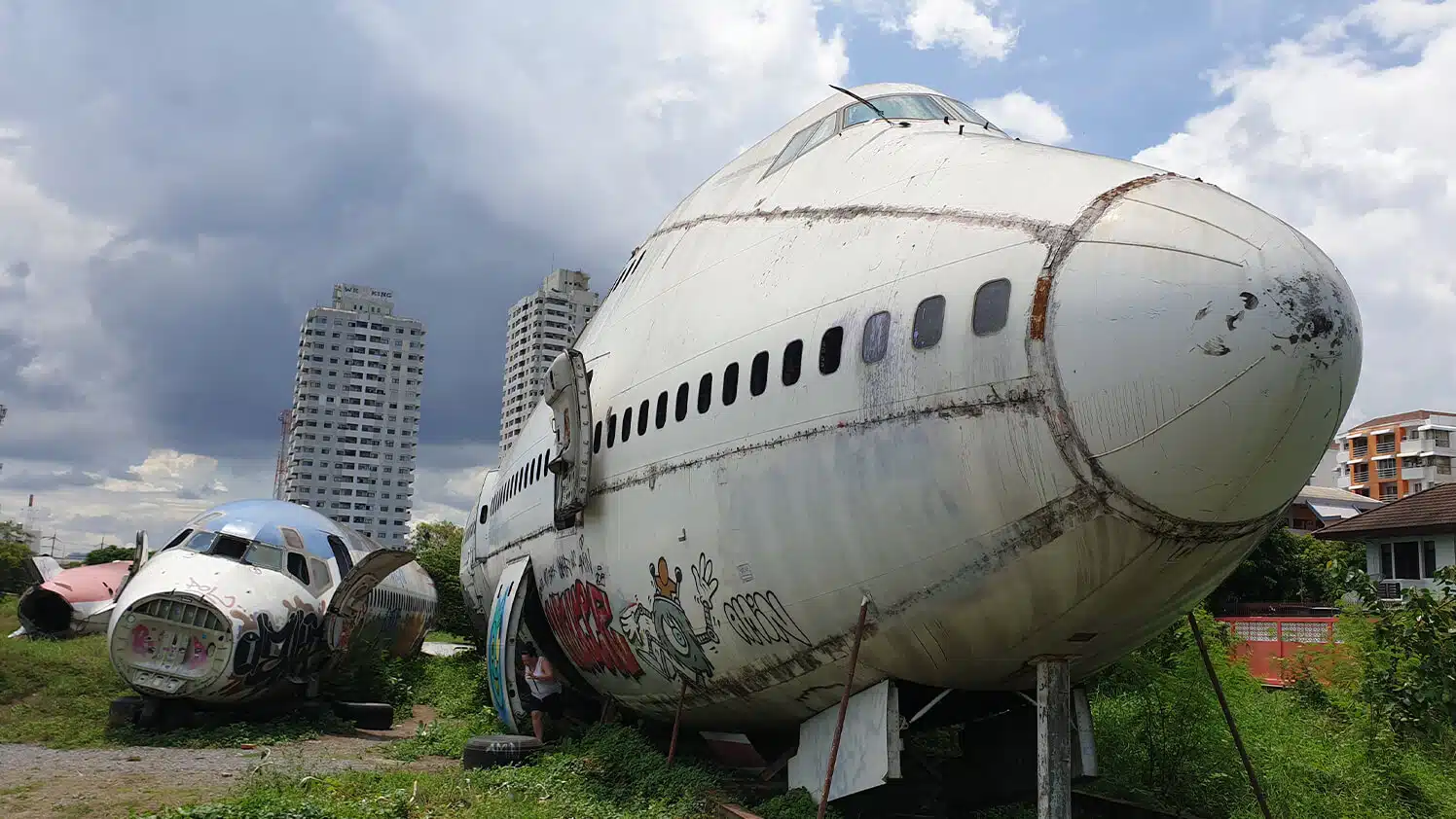
The picture of the Boeing 747 you see below will be our example input image. That is, it’s not the actual BMP image that’s embedded in this blog post. That wouldn’t be possible. It’s a JPEG representation of the BMP image we will read in our testbench. You can request the original BMP image by leaving your email address in the form above, and you will receive it straight away in your inbox.
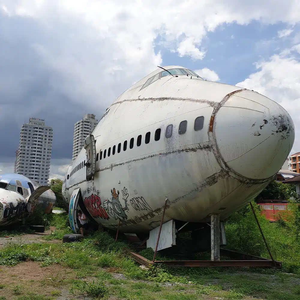
The test image is 1000 x 1000 pixels large. Although the code presented in this article should work with any image dimensions as long as it’s in the BITMAPINFOHEADER 24-bit BMP format. However, reading in a large image will take a lot of simulation time because file access in most VHDL simulators is slow. This image is 2930 kB and takes a few seconds to load in ModelSim.
Import the TEXTIO library
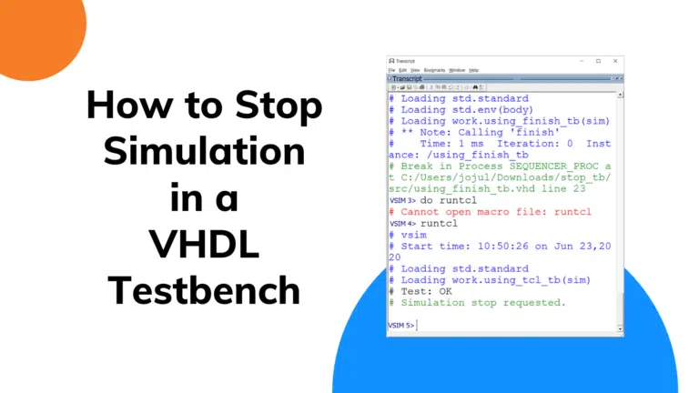
To read from or write to files in VHDL, you need to import the TEXTIO library. Make sure that you include the lines from the listing below at the top of your VHDL file. We also need to import the finish keyword from the standard package to stop the simulation when all tests have completed.
use std.textio.all;
use std.env.finish;
The above statements require VHDL-2008 or newer to be used.
Custom type declarations
We will declare a few custom types at the start of the declarative region of our testbench. The format of the data structures for storing pixel data depends on what kind of input the DUT expects. The grayscale module expects three bytes that each represent one of the color components red, green, and blue. Because it operates on one pixel at a time, we are free to store the pixel set as we want.
As we can see from the code below, we first declare a header_type array, which we will use to store all the header data. We will examine some fields within the header, but we also need to store it because we will write the processed image data to a new file at the end of the testbench. Then, we need to include the original header in the output image.
type header_type  is array (0 to 53) of character;

type pixel_type is record
  red : std_logic_vector(7 downto 0);
  green : std_logic_vector(7 downto 0);
  blue : std_logic_vector(7 downto 0);
end record;

type row_type is array (integer range <>) of pixel_type;
type row_pointer is access row_type;
type image_type is array (integer range <>) of row_pointer;
type image_pointer is access image_type;
The second statement declares a record named pixel_type. This custom type will act as a container for the RGB data for one pixel.
Finally, the dynamic data structures for storing all pixels are declared. While row_type is an unconstrained array of the pixel_type, the row_pointer is an access type to it, a VHDL pointer. Similarly, we construct an unconstrained image_type array to store all the rows of pixels.
Thus, the image_pointer type will function as a handle to the full image in dynamically allocated memory.
Instantiating the DUT
At the end of the declarative region, we declare the interface signals for the DUT, as shown below. The input signals are postfixed with _in and the output signals with _out. This allows us to easily identify them in the code as well as in the waveform. The DUT is instantiated at the start of the architecture with the signals assigned through the port map.
signal r_in : std_logic_vector(7 downto 0);
signal g_in : std_logic_vector(7 downto 0);
signal b_in : std_logic_vector(7 downto 0);
signal r_out : std_logic_vector(7 downto 0);
signal g_out : std_logic_vector(7 downto 0);
signal b_out : std_logic_vector(7 downto 0);

begin

DUT :entity work.grayscale(rtl)
port map (
  r_in => r_in,
  g_in => g_in,
  b_in => b_in,
  r_out => r_out,
  g_out => g_out,
  b_out => b_out
);
Process variables and file handles
We will create a single testbench process to contain all of the file reading and writing. The declarative region of the process is shown below. We start by declaring a new char_file type to define the data type that we wish to read from the input image file. The BMP file is binary encoded. Therefore, we want to operate on bytes, the character type in VHDL. On the next two lines, we use the type to open an input and an output file.
process
  type char_file is file of character;
  file bmp_file : char_file open read_mode is "boeing.bmp";
  file out_file : char_file open write_mode is "out.bmp";
  variable header : header_type;
  variable image_width : integer;
  variable image_height : integer;
  variable row : row_pointer;
  variable image : image_pointer;
  variable padding : integer;
  variable char : character;
begin
Next, we declare a variable to contain the header data, as well as two integer variables for holding the width and height of the image. After that, we declare a row pointer and an image pointer. The latter one will be our handle to the complete image once it has been read from file.
Finally, we declare two convenience variables; padding of type integer and char of type character. We will use these to store values that we read from the file temporarily.
Reading the BMP header
At the start of the process body, we read the entire header from the BMP file into the header variable, as shown in the code below. The header is 54 bytes long, but instead of using the hard-coded value, we get the range to iterate over by referencing the header_type'range attribute. You should always use attributes when you can to keep the constant values defined in as few places as possible.
for i in header_type'range loop
  read(bmp_file, header(i));
end loop;
Then follows a few assert statements where we check that some of the header fields are as expected. This is a safeguard against user error, as we don’t use the read values for anything; we just check that they are as expected. The expected values are the ones listed in this table, shown earlier in the article.
The code below shows the assert statements, each with a report statement describing the error and a severity failure statement to stop the simulation if the asserted expression is false. We need to use a raised severity level because, at least with the default settings in ModelSim, it will just print an error message and continue the simulation.
-- Check ID field
assert header(0) = 'B' and header(1) = 'M'
  report "First two bytes are not ""BM"". This is not a BMP file"
  severity failure;

-- Check that the pixel array offset is as expected
assert character'pos(header(10)) = 54 and
  character'pos(header(11)) = 0 and
  character'pos(header(12)) = 0 and
  character'pos(header(13)) = 0
  report "Pixel array offset in header is not 54 bytes"
  severity failure;

-- Check that DIB header size is 40 bytes,
-- meaning that the BMP is of type BITMAPINFOHEADER
assert character'pos(header(14)) = 40 and
  character'pos(header(15)) = 0 and
  character'pos(header(16)) = 0 and
  character'pos(header(17)) = 0
  report "DIB headers size is not 40 bytes, is this a Windows BMP?"
  severity failure;

-- Check that the number of color planes is 1
assert character'pos(header(26)) = 1 and
  character'pos(header(27)) = 0
  report "Color planes is not 1" severity failure;

-- Check that the number of bits per pixel is 24
assert character'pos(header(28)) = 24 and
  character'pos(header(29)) = 0
  report "Bits per pixel is not 24" severity failure;
Then we read the image width and height fields from the header. These are the only two values that we are actually going to use. Therefore, we assign them to the image_width and image_height variables. As we can see from the code below, we have to multiply the subsequent bytes by the weighted power of two values to convert the four-byte header fields into proper integer values.
-- Read image width
image_width := character'pos(header(18)) +
  character'pos(header(19)) * 2**8 +
  character'pos(header(20)) * 2**16 +
  character'pos(header(21)) * 2**24;

-- Read image height
image_height := character'pos(header(22)) +
  character'pos(header(23)) * 2**8 +
  character'pos(header(24)) * 2**16 +
  character'pos(header(25)) * 2**24;

report "image_width: " & integer'image(image_width) &
  ", image_height: " & integer'image(image_height);
Finally, we print the read height and width to the simulator console by using the report statement.
Reading the pixel data
We need to find out how many bytes of padding there will be on each line before we can start reading in the pixel data. The BMP format requires that each row of pixels is padded to a multiple of four bytes. In the code below, we take care of this with a one-liner formula using the modulo operator on the image width.
-- Number of bytes needed to pad each row to 32 bits
padding := (4 - image_width*3 mod 4) mod 4;
We also have to reserve space for all the rows of pixel data that we’re going to read. The image variable is an access type, a VHDL pointer. To make it point to a writable memory space, we use the new keyword to reserve space for image_height number of rows in dynamic memory, as shown below.
-- Create a new image type in dynamic memory
image := new image_type(0 to image_height - 1);
Now it is time to read the image data. The listing below shows the for-loop, which reads the array of pixels, row by row. For each row, we reserve space for a new row_type object, pointed to by the row variable. Then, we read the expected number of pixels, first the blue, then the green, and finally the red color. This is the ordering according to the 24-bit BMP standard.
for row_i in 0 to image_height - 1 loop

  -- Create a new row type in dynamic memory
  row := new row_type(0 to image_width - 1);

  for col_i in 0 to image_width - 1 loop

    -- Read blue pixel
    read(bmp_file, char);
    row(col_i).blue :=
      std_logic_vector(to_unsigned(character'pos(char), 8));

    -- Read green pixel
    read(bmp_file, char);
    row(col_i).green :=
      std_logic_vector(to_unsigned(character'pos(char), 8));

    -- Read red pixel
    read(bmp_file, char);
    row(col_i).red :=
      std_logic_vector(to_unsigned(character'pos(char), 8));

  end loop;

  -- Read and discard padding
  for i in 1 to padding loop
    read(bmp_file, char);
  end loop;

  -- Assign the row pointer to the image vector of rows
  image(row_i) := row;

end loop;
After reading the payload for each line, we read and discard the extra padding bytes (if any). Finally, at the end of the loop, we assign the new dynamic row of pixels to the correct slot of the image array. When the for-loop terminates, the image variable should contain pixel data for the entire BMP image.
Testing the DUT
The grayscale module uses only combinational logic, so we don’t need to worry about any clock or reset signals. The code below goes through every pixel in every row while writing the RGB values to the DUT inputs. After assigning the input values, we wait for 10 nanoseconds to let all the delta cycle delays within the DUT unwind. Any time values larger than 0 will work, or even wait for 0 ns; repeated enough times.
for row_i in 0 to image_height - 1 loop
  row := image(row_i);

  for col_i in 0 to image_width - 1 loop

    r_in <= row(col_i).red;
    g_in <= row(col_i).green;
    b_in <= row(col_i).blue;
    wait for 10 ns;

    row(col_i).red := r_out;
    row(col_i).green := g_out;
    row(col_i).blue := b_out;

  end loop;
end loop;
When the program comes out of the wait statement, the DUT outputs should contain the RGB values for the grayscale color for this pixel. At the end of the loop, we let the DUT output replace the pixel values that we read from the input BMP file.
Writing the output BMP file
At this point, all of the pixels in the image variable should have been manipulated by the DUT. It is time to write the image data to the out_file object, which points to a local file named “out.bmp”. In the code below, we run through every pixel in the header bytes, which we have stored from the input BMP file, and write them to the output file.
for i in header_type'range loop
  write(out_file, header(i));
end loop;
After the header, we need to write the pixels in the order that we read them from the input file. The two nested for-loops in the listing below take care of that. Note that after each row, we use the deallocate keyword to free the dynamically allocated memory for each row. Garbage collection is only included in VHDL-2019. In previous versions of VHDL, you could expect memory leaks if you omitted this line. At the end of the for-loop, we write padding bytes if needed to bring the row length to a multiple of 4 bytes.
for row_i in 0 to image_height - 1 loop
  row := image(row_i);

  for col_i in 0 to image_width - 1 loop

    -- Write blue pixel
    write(out_file,
      character'val(to_integer(unsigned(row(col_i).blue))));

    -- Write green pixel
    write(out_file,
      character'val(to_integer(unsigned(row(col_i).green))));

    -- Write red pixel
    write(out_file,
      character'val(to_integer(unsigned(row(col_i).red))));

  end loop;

  deallocate(row);

  -- Write padding
  for i in 1 to padding loop
    write(out_file, character'val(0));
  end loop;

end loop;
After the loop has terminated, we deallocate the memory space for the image variable, as shown below. Then we close the files by calling file_close on the file handles. This is not strictly necessary in most simulators because the file is implicitly closed when the subprogram or process terminates. Nevertheless, it’s never wrong to close files when you are done with them.
  deallocate(image);

  file_close(bmp_file);
  file_close(out_file);

  report "Simulation done. Check ""out.bmp"" image.";
  finish;
end process;
At the end of the testbench process, we print a message to the ModelSim console that the simulation is over, with a hint of where the output image can be found. The finish keyword requires VHDL-2008. It’s an elegant way to stop the simulator after all test cases have completed.
Need the Questa/ModelSim project files?
Let me send you a Zip with everything you need to get started in 30 seconds
Tested on Windows and Linux Loading Gif..
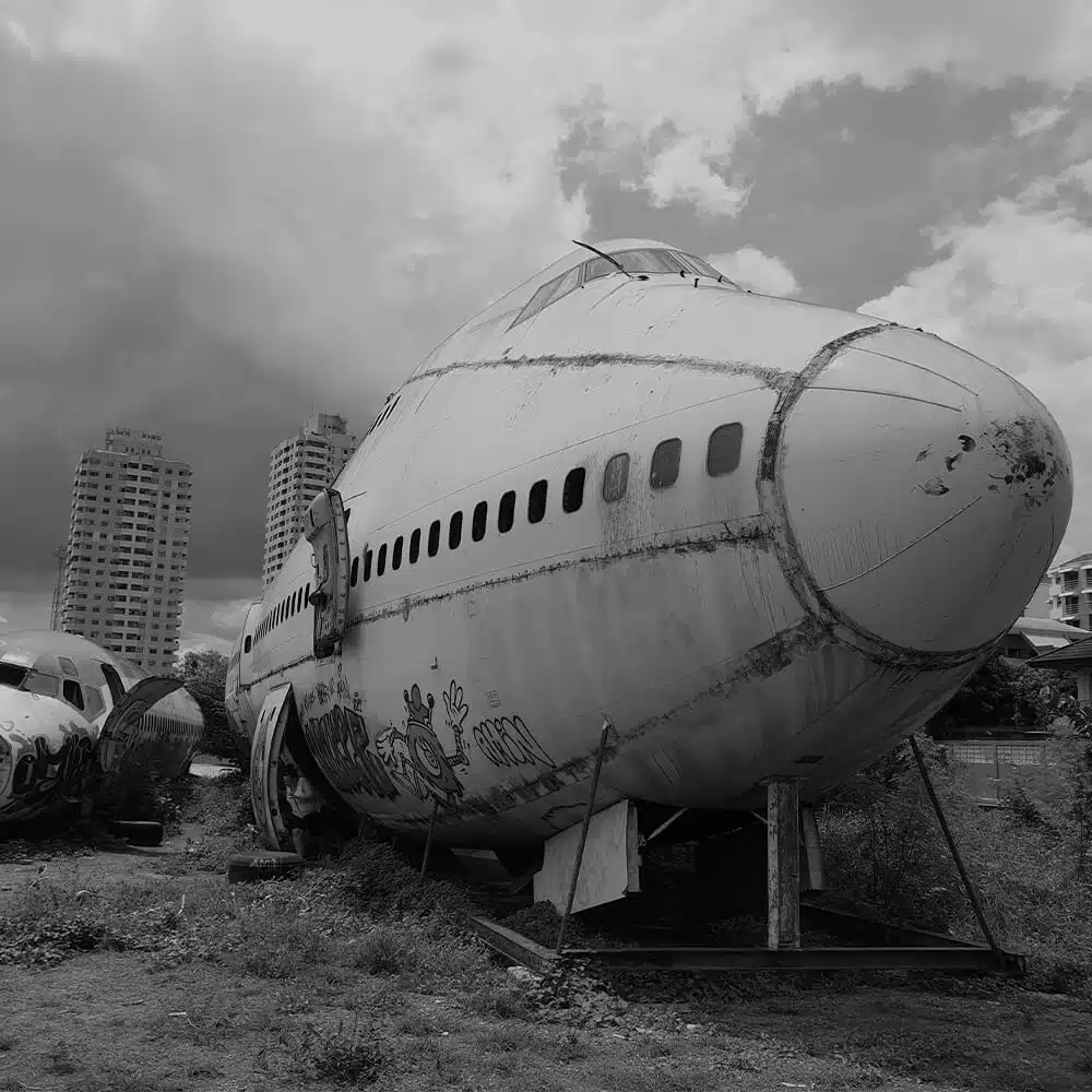
The output BMP image
The image below shows what the “out.bmp” file looks like after the testbench has completed. The actual file shown in this blog post is a JPEG because BMPs are unsuitable for embedding on webpages, but you can leave your email address in the form above to get a zip with the full project, including the “boeing.bmp” file.
Last remarks
For image processing in FPGAs, the YUV color encoding scheme is often used instead of RGB. In YUV, the luma (luminance) component, Y, is kept separate from the color information. The YUV format is more closely mapped to human visual perception. Fortunately, it’s easy to convert between RGB and YUV.
Converting RGB to CMYK is a bit more complicated because there isn’t a one-to-one pixel formula.
Another alternative when using such exotic encoding schemes is to invent your own image file format. Simply store the pixel arrays in a custom file format suffixed by “.yuv” or “.cmyk”. There’s no need for a header when you know what kind of image format the pixels will have; just go ahead and read it in your testbench.
You can always incorporate a software conversion into your design flow. For example, automatically convert a PNG image to the BMP format by using standard command-line image conversion software before the simulation starts. Then, read it in your testbench using VHDL as you have learned from this article.

I want to get the files for this project.
To request the project files, find the “Need the ModelSim project files?” form in this blog post. Enter your email address and click the “GIVE ME THE FILES!” button. You should receive a Zip file in your inbox within a minute.
“GIVE ME THE FILES!”
You are not supposed to write it here. Use the form in the article to request the files.