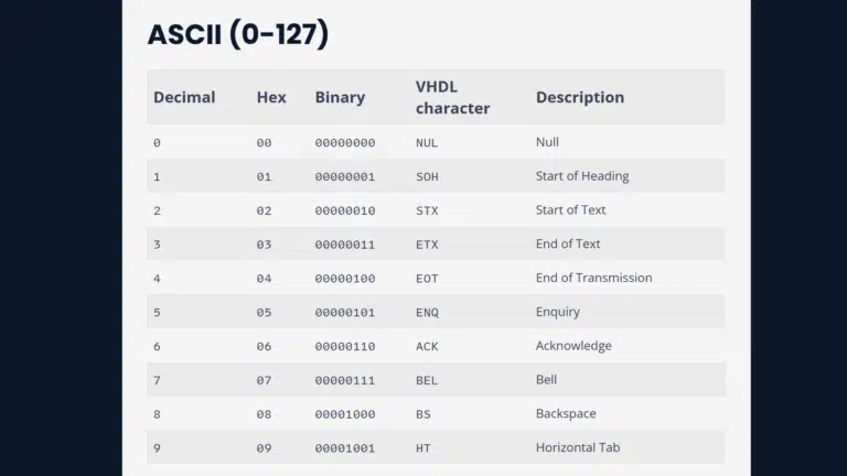
The previously discussed filter describes a general-purpose device that can fit in many applications but is not necessarily the optimal solution. This is where application-specific FIR structures come in. Therefore, this post aims to present some of the more popular filter structures used in specialized applications.
Category: In-depth
As an FPGA designer, you have the freedom to implement the (finite impulse response) FIR filter either parallel or in series. Read the article to find out how to implement a FIR filter using VHDL!
Finite Impulse Response (FIR) and Infinite Impulse Response (IIR) are the two types of digital filters you’re most likely to use in FPGAs. This article discusses the implementation of the filters seen from the eyes of a hardware developer.
The ‘stable and ‘quiet attributes are predefined in the VHDL standard and work on signal objects. We can use these special features in simulation to check that a signal’s value remains untouched for a given period.
A latch is a logic element that can sample and hold a binary value, much like a flip-flop (register). But unlike a flip-flop, which is edge-triggered, the latch is level-triggered.
This article examines how we can use configuration constructs to create variants of a module or testbench without maintaining multiple versions of the file. We will also look at other use cases for configuration declarations in VHDL design.
Configurations have been part of the VHDL standard since the first version of the language. But still, many FPGA designers never use them, perhaps because few people understand how configurations work.
I find that unfortunate because it’s really not that complicated.
There are two ways to instantiate a module in VHDL: component instantiation and entity instantiation. Some people refer to the latter as direct instantiation.
Entity instantiation didn’t exist in the first revisions VHDL, but it has been available since VHDL’93. This is the method that I recommend unless you have specific reasons to use component instantiation.
To use the component instantiation method, you first have to declare the component in the declarative scope of where you want the module instance.
When you have worked with VHDL code written by many other FPGA engineers, you are bound to notice that there are two common ways to model an edge detector in VHDL. There’s the rising_edge(clk) statement, and there’s the old style clk’event and clk = ‘1’ method.
The two if-statements do the same thing once the code is on the FPGA. They postulate that whatever is inside of the if-statement happens on the rising edge of the trigger signal,
There are many ways to create a shift register in VHDL, though not all of them are equal. You can dramatically reduce the number of consumed resources by choosing the right shift register implementation for your needs and FPGA architecture.
VHDL includes few built-in types but offers several additional types through extension packages. Two of the most widely used types are std_logic and std_ulogic. The difference between them is that the former is resolved while the latter isn’t.
Before we go on to investigate what it means that a type is resolved, let’s first look at the traits that the two types share in common.
Bit and boolean are part of the standard package,