The ready/valid hardware data transfer protocol is simple and ingenious, providing flow control with only two control signals. The rules are straightforward: data transfer only happens when both ready and valid are '1' during the same clock cycle.
The AMBA AXI protocol uses the ready/valid handshake signals for flow control on all its hardware data buses. Therefore, many developers associate the ready/valid naming scheme with AXI, but it’s a fundamental flow control mechanism that you should know about even if you’re not using AXI.
Click here to read more about the pipelining coding challenge! (as mentioned in the video above)
Click here to read about the VHDLwhiz Membership and join!
Using the ready/valid handshake
The ready/valid handshake is a stateless protocol. Neither party needs to remember what happened in previous clock cycles to determine if a data transfer occurs in the current cycle.
Furthermore, both parties must operate synchronously and read the control signals on the same clock edge. Because of that, ready/valid isn’t appropriate for clock domain crossing.
Interface signals
The diagram below shows a VHDL module with one output bus that uses ready/valid handshaking. While ready is the receiver’s key to limiting the data flow into it, the sender controls the valid and data signals. Both parties can throttle the data rate, and transfers only happen when both agree.
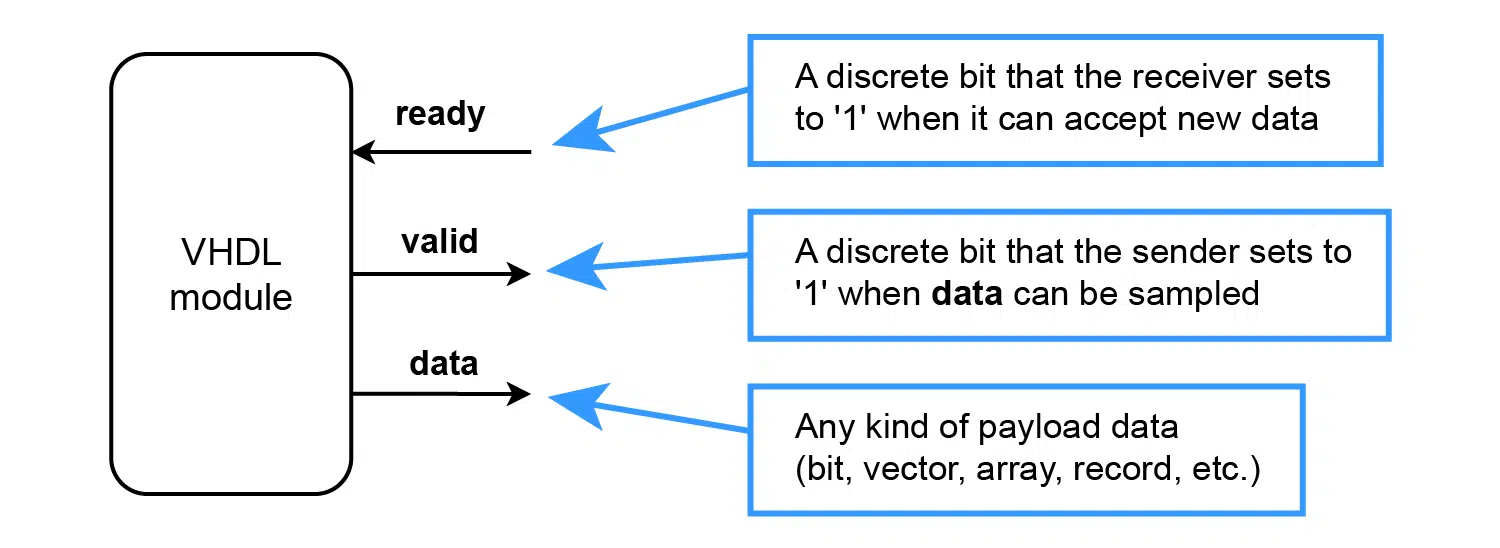
Receiver and sender interface
(Also called transmitter/receiver, data source/sink, or master/slave interface)
Stream processing VHDL modules typically have input and output interfaces. That’s because they sit on the data path and do various transformations on the data before passing it on to downstream modules.
The diagram below shows the outline of such a module. Notice that the input and output buses have identical names but with the data directions swapped.
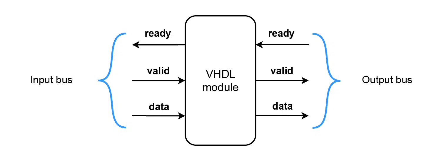
The listing below is from the pipelining coding challenge. It shows the entity of a VHDL module corresponding to the diagram above. The input signals are prefixed with in_ and the outputs with out_. Every signal’s in/out modes are opposite on the input and output buses, as in the diagram.
entity pipeline is
  port (
    clk : in std_logic;
    rst : in std_logic;

    -- Input bus
    in_ready : out std_logic;
    in_valid : in std_logic;
    in_data : in std_logic_vector(23 downto 0);

    -- Output bus
    out_ready : in std_logic;
    out_valid : out std_logic;
    out_data : out std_logic_vector(23 downto 0)
  );
end pipeline;
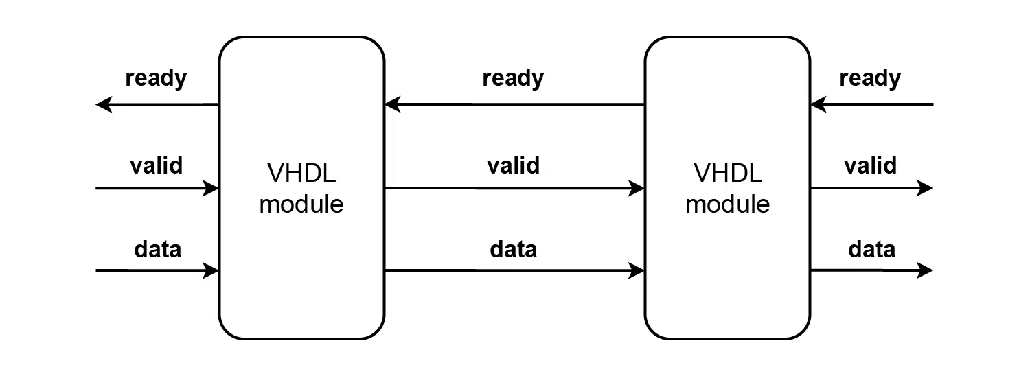
Connecting two modules
Unlike req/ack- or tx/rx-based protocols, ready/valid signals go to the signals with matching names when connecting sender and receiver modules. That makes it easier to navigate the VHDL project.
The signals connecting two modules will have the same names as the entity signals they connect to, regardless if we are viewing from the perspective of the sender or the receiver. You can see the benefit in the diagram below, showing two interconnected modules with identical interfaces.
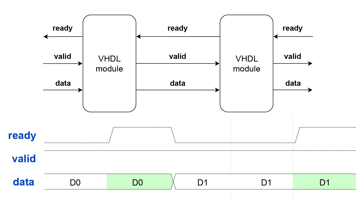
Example waveforms
The ready/valid handshake rules are simple: data transfer happens when ready and valid are '1' during the same clock cycle, but let’s look at some practical examples to consolidate further your understanding of how this flow control protocol works.
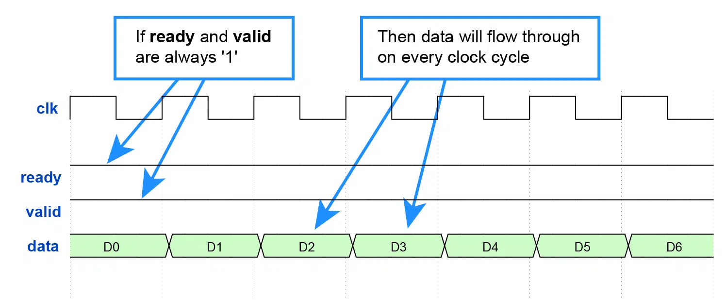
Sending and receiving at full speed
The simplest example I can think of is when ready and valid are '1' continuously. Then, data flows through the interface unhindered, with one transaction on every clock cycle. It’s as if there was no flow control.
Slow writer and fast reader
In this example, the ready signal is always '1' while the sender asserts valid occasionally.
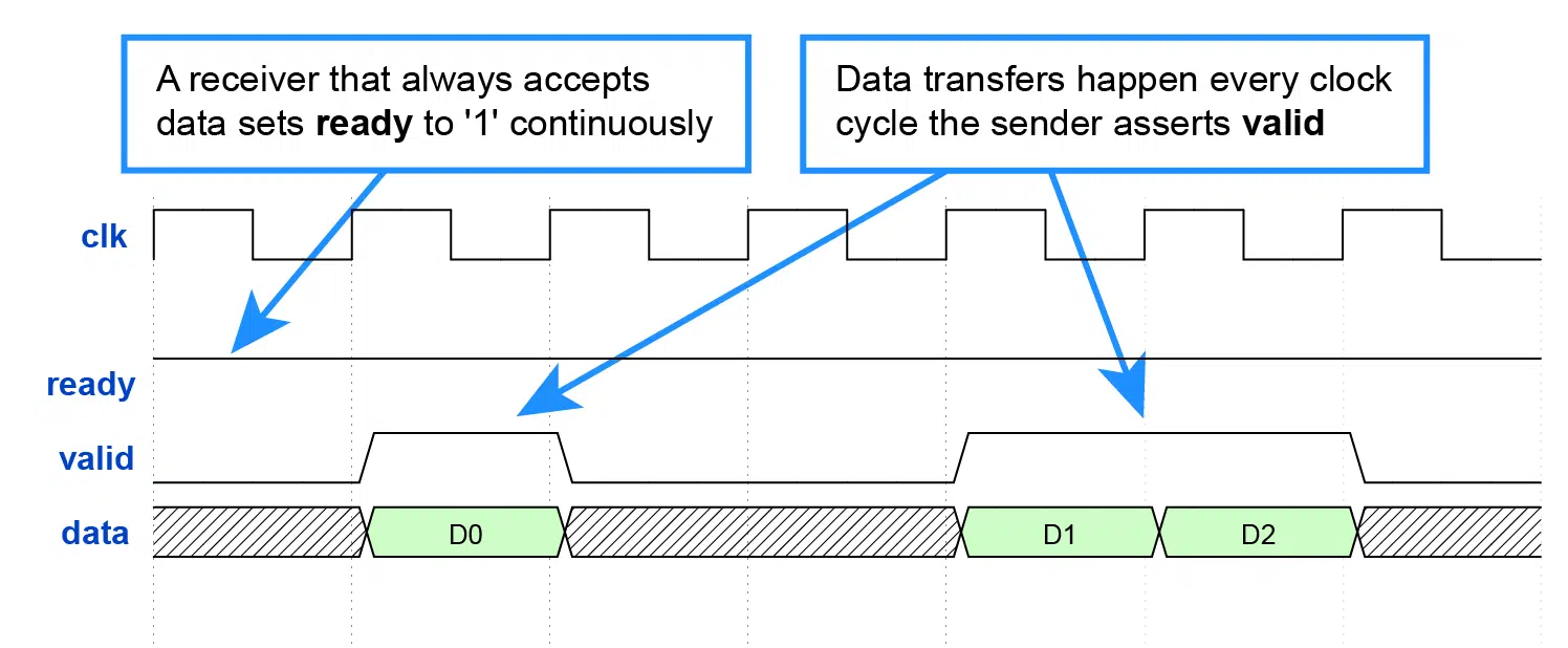
When implementing a reader module that is guaranteed to accept a data item on every clock cycle, you can simply hardwire ready to always accept data:
ready <= '1';
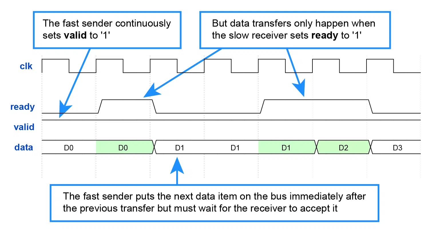
Fast writer and slow reader
This waveform shows a situation where the reader module is throttling the data rate. We say that the downstream module exerts backpressure when it pauses the data stream like that.
Irregular read/write pattern
The writer has no obligation to keep the data on the bus until it’s read. It can put it on the bus on one clock cycle and remove it on the next. It’s legal* in the ready/valid handshake, although I can’t see why anyone would make such a module.
* The AXI Stream protocol doesn’t permit this behavior. Thanks to Sławomir from the comment section for this quote from the AXI specification:
A master is not permitted to wait until TREADY is asserted before asserting TVALID. Once TVALID is asserted it must remain asserted until the handshake occurs.
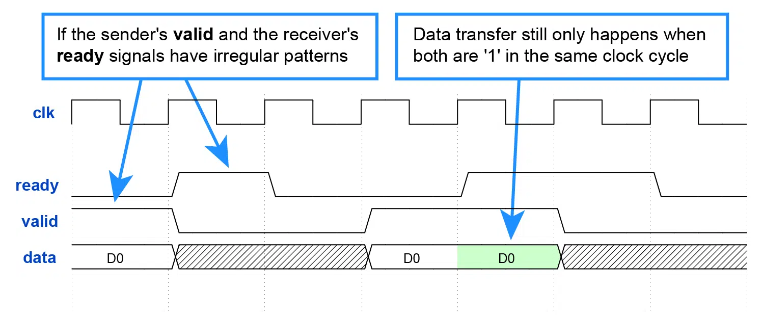
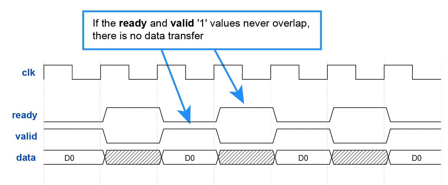
Non-overlapping read/write pattern
Finally, let’s look at an example where ready and valid switch continuously, but no data passes through.
Hopefully, you won’t see this behavior in an RTL design, but it’s useful to understand why it’s like that. Though, it has happened in my testbenches when writing creative test patterns.
Challenge: Pipelining with AXI-style ready/valid flow control
To make learning VHDL fun, I’ve created a coding challenge where you can practice getting the ready/valid handshake right.
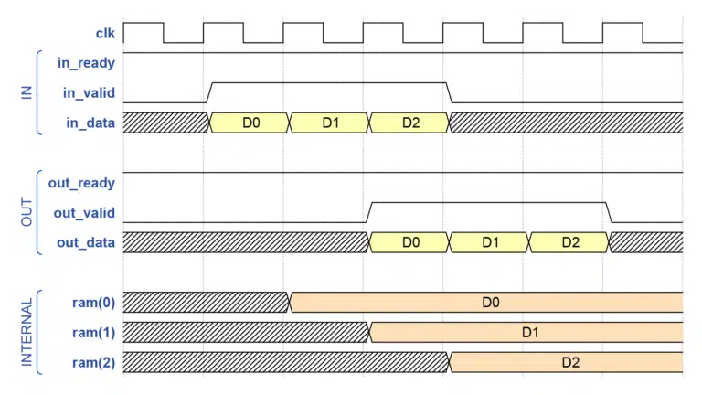
In the competition, I provide a module with a self-checking testbench. The module works fine and runs through all the test cases. But the module’s operation is complex and should be split over multiple clock cycles to ease timing.
Your task is to convert the example module to a pipelined design that uses three clock cycles instead of one without limiting the throughput. It should still run through the same self-checking testbench.
After one week, I will post a video explaining half of my proposed solution, which should make it easier. Finally, I will reveal my complete solution after two weeks and explain how it works.
If you are viewing this video sometime in the future, the hint and solution videoes will already be waiting for you on the challenge page. You can still join the membership and take the challenge.
Here’s a direct link to the challenge page in the Membership portal (only accessible for members)
You click the banner below to join the membership and gain access to the challenge today!

Click here to read more about the VHDLwhiz Membership and join!

Hi, nice article, thank you for great resources. One comment abut deasserting tvalild when tready is 0.
> It’s legal according to the protocol, although I can’t see why anyone would make such a module.
If you mean AXI Stream protocol its explicitly prohibited in specification:
> A master is not permitted to wait until TREADY is asserted before asserting TVALID. Once
> TVALID is asserted it must remain asserted until the handshake occurs.
Thanks! I’ve updated the IRREGULAR READ/WRITE PATTERN section with your sidenote. 👍
Not just for AXI4-Stream, the whole AXI specification in general specifies that VALID can not be de-asserted before a READY is received.
Have a look at the Handshake process in AMBA AXI and ACE specification (version H.c.) Chapter A3.2.1.