Most VHDL simulators use the Tool Command Language (Tcl) as their scripting language. When you type a command in the simulator console, you are using Tcl. Furthermore, you can create scripts with Tcl that run in the simulator and interact with your VHDL code.
In this article, we will create a self-checking testbench that uses Tcl instead of VHDL to verify that a VHDL module behaves correctly.
See also:
Why you need to learn Tcl
Interactive testbench using Tcl
You can download the code from this article and the ModelSim project using the form below.
Need the Questa/ModelSim project files?
Let me send you a Zip with everything you need to get started in 30 seconds
Tested on Windows and Linux Loading Gif.. 
The DUT: A code lock module in VHDL
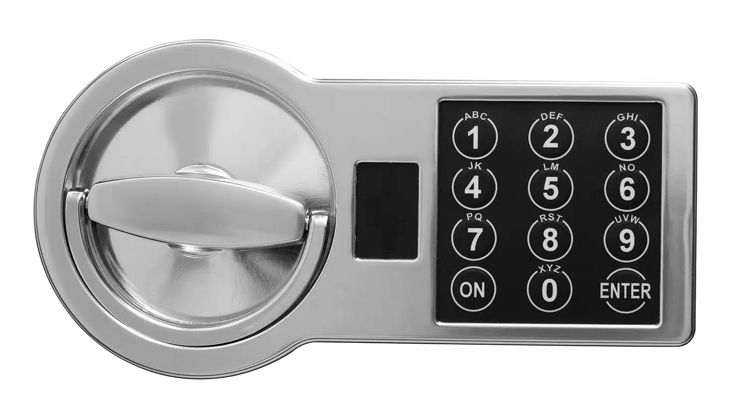
Before we start on the testbench, I will present the device under test (DUT). It will be a code lock module that will unlock a vault when we enter the correct number sequence on a PIN pad.
People often refer to a code lock as a combination lock. However, I find this term to be inaccurate. It’s not enough to enter the correct combination of digits to unlock it. You also have to enter them in the right order. Strictly speaking, a combination lock is really a permutation lock, but let’s call it a code lock.
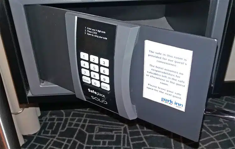
The image above shows such a code lock in the form of a hotel safe. For simplicity, our example will only use the number keys and not the “CLEAR” and “LOCK” buttons.
How the code lock module works
Our module will start in the locked position, and if we enter four digits in a row that match the secret PIN code, it will unlock the safe. To relock it, we can enter another incorrect number. Thus, we need to create a sequence detector in VHDL.

The waveform above shows how the code lock module is going to work. Apart from the clock and reset, there are two input signals: input_digit and input_enable. The module shall sample the input digit when the enable is ‘1’ on a rising clock edge.
There is only one output from this module: the unlock signal. Imagine that it controls the locking mechanism of a safe or a vault of some kind. The unlock signal shall only be ‘1’ only when the user has entered four consecutive digits that match the correct PIN. In this article, we will use 1234 as the passcode.
The entity
The code below shows the entity of the code lock module. Because this module’s purpose is to be a simple example DUT for our TCL-based testbench, I’m hard-coding the secret passcode using generics. The four generic constants are binary coded decimals (BCDs) realized as integers with a restricted range.
entity code_lock is
  generic (pin0, pin1, pin2, pin3 : integer range 0 to 9);
  port (
    clk : in std_logic;
    rst : in std_logic;
    input_digit : in integer range 0 to 9;
    input_enable : in std_logic;
    unlock : out std_logic
  );
end code_lock;
Just like the passcode, the input_digit signal is also a BCD type. The other inputs and outputs are std_logics.
The declarative region
This module has only one internal signal: a shift register that contains the last four digits that the user has typed. But instead of using the BCD range of 0 to 9, we let the numbers go from -1 to 9. That’s 11 possible values.
type pins_type is array (0 to 3) of integer range -1 to 9;
signal pins : pins_type;
We have to use a reset value which isn’t a digit that the user can enter, and that’s what the -1 is for. If we had used the range 0 to 9 for the pins array, setting the secret passcode to 0000 would have initially opened the vault. With this scheme, the user will explicitly have to enter four 0’s.
The implementation
At the top of the architecture region, I’ve added a concurrent statement that unlocks the vault when the pins signal matches the generic constants. The code below is combinational, but since the pins signal is clocked, the unlock signal will only change on the rising edge of the clock.
unlock <= '1' when pins = (pin3, pin2, pin1, pin0) else '0';
The code below shows the process that reads the user input. It makes a shift register out of the pins signal by shifting all the values when input_enable is ‘1’ on a rising clock edge. The result is that the four last digits that the user has entered get stored in the pins array.
PINS_PROC : process(clk)
begin
  if rising_edge(clk) then
    if rst = '1' then
      pins <= (others => -1);

    else

      if input_enable  = '1' then
        pins(0) <= input_digit;
        pins(1 to 3) <= pins(0 to 2);
      end if;

    end if;
  end if;
end process;
The VHDL testbench
First of all, we still need a basic VHDL testbench, even though we are using Tcl for the verification. The code below shows the complete VHDL file. I’ve instantiated the DUT and created the clock signal, but that’s all. Apart from generating the clock, this testbench does nothing.
library ieee;
use ieee.std_logic_1164.all;

entity code_lock_tb is
end code_lock_tb;

architecture sim of code_lock_tb is

  constant clk_hz : integer := 100e6;
  constant clock_period : time := 1 sec / clk_hz;

  signal clk : std_logic := '1';
  signal rst : std_logic := '1';
  signal input_digit : integer range 0 to 9;
  signal input_enable : std_logic := '0';
  signal unlock : std_logic;

begin

  clk <= not clk after clock_period;

  DUT : entity work.code_lock(rtl)
    generic map (1,2,3,4)
    port map (
      clk => clk,
      rst => rst,
      input_digit => input_digit,
      input_enable => input_enable,
      unlock => unlock
    );

end architecture;
The Tcl testbench
The Tcl code in this example only works with the ModelSim VHDL simulator. If you want to use it in Vivado, for instance, you have to make some changes to it. That’s because it uses a few commands that are specific to this simulator. A drawback of using Tcl is that your code gets locked to a particular simulator vendor.
For reference, I recommend the Tcl Developer Xchange, which covers the Tcl language in general, and the ModelSim Command Reference Manual, which describes all the ModelSim-specific commands.
If you have ModelSim installed, you can download the example project using the form below.
Need the Questa/ModelSim project files?
Let me send you a Zip with everything you need to get started in 30 seconds
Tested on Windows and Linux Loading Gif..
Using a namespace
The first thing I recommend is to create a Tcl namespace. That’s a good idea because otherwise, you may unintentionally overwrite global variables from your Tcl script. By wrapping all of your code in the namespace, you avoid that potential mess. We will put all the Tcl code we write from now on inside the codelocktb namespace, as shown below.
namespace eval ::codelocktb {

  # Put all the Tcl code in here

}
Inside the namespace, we have to begin by starting the simulation, as shown below. We do that with the vsim command, followed by the library and entity name of the VHDL testbench. That will load the simulation, but it won’t run it. No simulation time passes until we use the run command later in the script. I also like to include an If statement that will load the waveform, if it exists.
# Load the simulation
vsim work.code_lock_tb

# Load the waveform
if {[file exists wave.do]} {
  do wave.do
}
Declaring namespace variables
Now that we have loaded the simulation, we can start interacting with the VHDL code. First, I want to read the clock_period constant and passcode generic into the Tcl environment.
In the code below, I’m using the ModelSim-specific examine command to read VHDL signal and constant values in Tcl. Then, I’m using Tcl string and list commands to extract the time value and time units. The pinCode variable becomes a list of the four digits that we read from the generic constants.
# Read the clock period constant from the VHDL TB
variable clockPeriod [examine clock_period]

# Strip the braces: "{10 ns}" => "10 ns"
variable clockPeriod [string trim $clockPeriod "{}"]

# Split the number and the time unit
variable timeUnits [lindex $clockPeriod 1]
variable clockPeriod [lindex $clockPeriod 0]

# Read the correct PIN from the VHDL generics
variable pinCode [examine dut.pin0 dut.pin1 dut.pin2 dut.pin3]
Note that I’m using a different coding style in the Tcl script than in the VHDL code. Instead of underscores, I’m using camel casing. That’s because I’m following the Tcl style guide. Of course, nothing stops you from using the same style in the Tcl and VHDL files if that’s what you prefer.
Also, if you have used Tcl without namespaces, you probably know about the set keyword, which is the standard way of defining a variable in Tcl. Here, I’m using the newer variable keyword instead. It’s like a global variable that’s tied to the current namespace instead of the global scope.
Finally, we declare a variable named errorCount and initialize it to 0, as shown below. As the simulation proceeds through the test cases, we will increment it every time we detect an error. In the end, we can use it to determine if the module passed or failed.
variable errorCount 0
Printing text in ModelSim
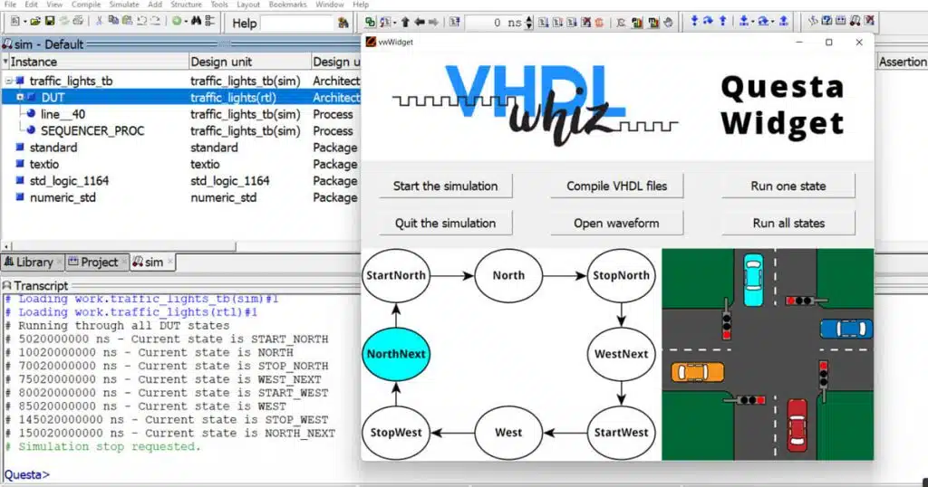
The puts command is the standard way of printing text to the console in Tcl. But this method works in an unfortunate way in ModelSim. The Windows version does what you would expect; it prints the string to the console. In the Linux version, on the other hand, the text is output in the shell where you started ModelSim from, and not in the console within the GUI.
The image below shows what happens when we type the puts command in the ModelSim console. It appears in the terminal window behind. Even worse, if you started ModelSim using a desktop shortcut, you won’t ever see the output because the shell is hidden.
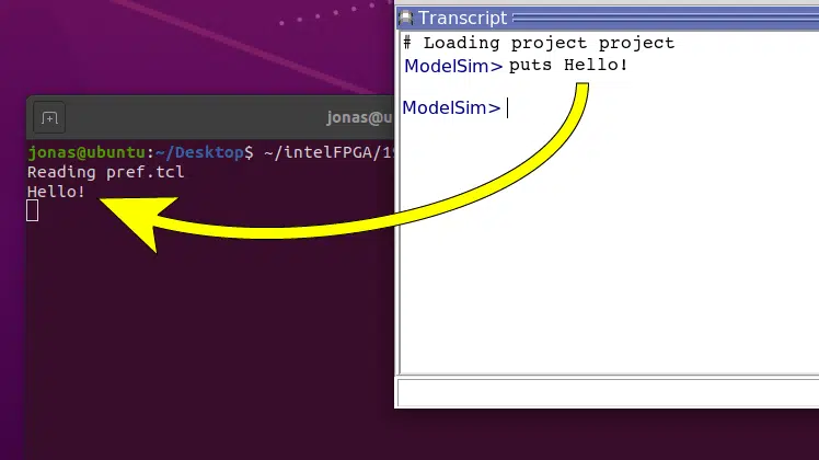
There are workarounds to change the behavior of the puts command. You can, for example, redefine it (Yes! You can do that in Tcl) and make it work on both platforms. But a more straightforward way to print the text to the console in both Linux and Windows is to use the ModelSim-specific echo command.
We will use the custom Tcl procedure shown below to print text. And while doing so, we also prepend the message with the current simulation time. In ModelSim, you can always get it using the $now global variable.
proc printMsg { msg } {
  global now
  variable timeUnits
  echo $now $timeUnits: $msg
}
Simulating for N clock cycles
The DUT is a clocked module, meaning that nothing happens between the rising clock edges. Therefore, we want to simulate in steps based on the duration of a clock cycle. The Tcl procedure below uses the clockPeriod and timeUnits variables we lifted from the VHDL code earlier to achieve that.
proc runClockCycles { count } {
  variable clockPeriod
  variable timeUnits

  set t [expr {$clockPeriod * $count}]
  run $t $timeUnits
}
The procedure takes one parameter: count. We multiply it by the length of one clock period to get the duration of N clock cycles. Finally, we use the ModelSim run command to simulate for precisely that long.
Checking a signal value from Tcl
In ModelSim, we can read a VHDL signal from Tcl by using the examine command. The code below shows the Tcl procedure that we’re using to read a signal value and check that it’s as expected. If the signal doesn’t match the expectedVal parameter, we print a nasty message and increment the errorCount variable.
proc checkSignal { signalName expectedVal } {
  variable errorCount

  set val [examine $signalName]
  if {$val != $expectedVal} {
    printMsg "ERROR: $signalName=$val (expected=$expectedVal)"
    incr errorCount
  }
}
Testing a PIN sequence
The output from the code lock module depends not only on the current inputs but also on their previous values. Therefore, checking the outputs has to happen at least after sending four digits to the DUT. Only then should the unlock signal change from ‘0’ to ‘1’ if the PIN is correct.
The Tcl procedure below uses the ModelSim force keyword to change VHDL signals from Tcl. The -deposit switch to the force keyword means that ModelSim will change the value, but let another VHDL driver take control of it later, although no other entities are controlling the DUT inputs in our testbench.
proc tryPin { digits } {
  variable pinCode

  set pinStatus "incorrect"
  if { $digits == $pinCode } {
    set pinStatus "correct"
  }

  printMsg "Entering $pinStatus PIN code: $digits"

  foreach i $digits {
    force input_digit $i -deposit
    force input_enable 1 -deposit
    runClockCycles 1
    force input_enable 0 -deposit
    runClockCycles 1
  }

  if { $pinStatus == "correct" } {
    checkSignal unlock 1
  } else {
    checkSignal unlock 0
  }
}
The tryPin procedure uses our printMsg procedure to inform about what it is doing, which PIN code it is entering, and whether it is the correct passcode. It also uses the runClockCycles procedure to run for exactly one clock period, while manipulating the DUT inputs to simulate a user entering a PIN.
Finally, it uses the checkSignal procedure to verify that the DUT is behaving as expected. As I’ve already explained, the checkSignal procedure will print an error message and increment the errorCount variable if the unlock signal doesn’t match the expected value.
Test cases and finish status
In the above Tcl code, we have started the simulation, and we have defined a bunch of variables and procedures, but we haven’t simulated any time at all. The simulation is still at 0 ns. No simulation time has passed.
Towards the end of our custom namespace, we start calling the Tcl procedures. As shown in the code below, we begin by running for ten clock cycles. After that, we release the reset and check that the unlock output has the expected value of ‘0’.
runClockCycles 10

# Release reset
force rst '0' -deposit
runClockCycles 1

# Check reset value
printMsg "Checking reset value"
checkSignal unlock 0

# Try a few corner cases
tryPin {0 0 0 0}
tryPin {9 9 9 9}
tryPin $pinCode
tryPin [lreverse $pinCode]

if { $errorCount == 0 } {
  printMsg "Test: OK"
} else {
  printMsg "Test: Failure ($errorCount errors)"
}
We could try all of the 10000 different PIN codes, but that would take a considerable amount of time. Tcl-driven simulation is much slower than a pure VHDL testbench. The simulator has to start and stop a lot, and that takes a lot of time. Therefore, I’ve decided only to check corner cases.
We call tryPin four times, with the PIN codes: 0000, 9999, the correct PIN, and the numbers from the correct PIN in the opposite order. I imagine that this is an easy mistake to make when creating a code lock, to look at only the combination and not the ordering of the numbers.
Finally, at the very end of the Tcl code, but still within the namespace, we check the errorCount variable and print a “Test: OK” or a “Test Failure”.
Running the testbench
And now comes the fun part: running the testbench. I prefer to use the Tcl source command, as shown below, but you can also use the ModelSim-specific do command. In fact, ModelSim DO files are really just Tcl files with a different suffix.
source code_lock/code_lock_tb.tcl
In the final version of my code, there are no errors. The listing below shows the output from a successful simulation. The Tcl script informs us about what it’s doing, and we can see that all message lines have a timestamp. That’s our printMsg procedure at work. Finally, the testbench stops and prints “Test: OK”.
VSIM> source code_lock/code_lock_tb.tcl
# vsim
...
# 110 ns: Checking reset value
# 110 ns: Entering incorrect PIN code: 0 0 0 0
# 190 ns: Entering incorrect PIN code: 9 9 9 9
# 270 ns: Entering correct PIN code: 1 2 3 4
# 350 ns: Entering incorrect PIN code: 4 3 2 1
# 430 ns: Test: OK
However, I want to show you what it looks like when the DUT fails a test. To do that, I’ve created an error in the code lock module. I’ve replaced the checking of pin1 with pin2 so that the DUT ignores the pin1 value. It’s an easy typo to make, as shown in the code below.
unlock <= '1' when pins = (pin3, pin2, pin2, pin0) else '0';
When we now run the testbench, you can see from the listing below that the fault is detected. And finally, the testbench prints “Test: Failure” along with the number of errors.
VSIM> source code_lock/code_lock_tb.tcl
# vsim
...
# 110 ns: Checking reset value
# 110 ns: Entering incorrect PIN code: 0 0 0 0
# 190 ns: Entering incorrect PIN code: 9 9 9 9
# 270 ns: Entering correct PIN code: 1 2 3 4
# 350 ns: ERROR: unlock=0 (expected=1)
# 350 ns: Entering incorrect PIN code: 4 3 2 1
# 430 ns: Test: Failure (1 errors)
Need the Questa/ModelSim project files?
Let me send you a Zip with everything you need to get started in 30 seconds
Tested on Windows and Linux Loading Gif..
Final thoughts
I’ve created a lot of Tcl-based testbenches in my career, but my opinion on them is somewhat divided.
On the one hand, you can do some cool things that are not possible with VHDL alone. For example, the interactive testbench. It’s also nice that you can change the testbench without having to recompile. And finally, verification using a vastly different language can be advantageous. You would have to make the same mistake in two different technologies for it to pass undetected, and that’s unlikely.
On the other hand, there are some disadvantages too. The Tcl-based testbenches are magnitudes slower than their VHDL counterparts. Another significant issue is vendor lock-in. It’s impossible to create a fully portable Tcl testbench, while a VHDL testbench can run on any capable simulator.
And the final reason why Tcl testbenches may not be worth it is the language itself. It doesn’t have great features for preventing programming errors, and debugging a Tcl problem is difficult. It’s not an intuitive nor forgiving language like Python or Java.
However, it serves a purpose as a glue language between VHDL and the software world. And because most FPGA tools, not only simulators, support Tcl, I highly recommend learning it.
These thoughts are just my opinions. Tell me what you think in the comment section!


totally agree with your thoughts on VHDL v TCL benches,
use TCL, have vendor tie in , run slow , but not have to re compile
v
use VHDL 2008, run on any VHDL simulator, fast, but have to re compile when making changes to bench,
Its worrying how many people don’t know how to just re compile the bench , but quit modelsim and re start
I use VHDL-2008 too, and hopefully, VHDL-2019 soon. But it’s nice to have Tcl for other tasks. For example, creating scripts to compile and restart the simulation. 😄
Thanks for commenting!