
Constrained random verification is a testbench strategy that relies on generating pseudo-random transactions for the device under test (DUT). The goal is to reach functional coverage of a number of predefined events through random interaction with the DUT.
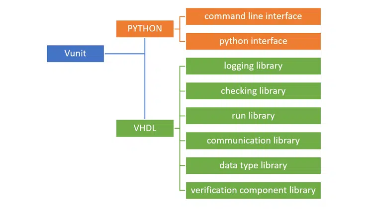
Open Source VHDL Verification Methodology (OSVVM) is a free VHDL library which includes a number of convenient packages for creating constrained random testbenches. We are particularly interested in the RandomPkg and CoveragePck, which we will be using in this article. I recommend visiting the OSVVM GitHub page to learn more about the features of this library.
The device under test
I’m going to dive right into an example to better explain how a constrained random testbench differs from the classic testbench, which uses directed tests. We created a ring buffer FIFO in the previous article on this blog, but we didn’t create a self-checking testbench to verify the correctness of the module.
We’re going to create a proper testbench for the ring buffer FIFO that uses constrained random verification.
entity ring_buffer is
  generic (
    RAM_WIDTH : natural;
    RAM_DEPTH : natural
  );
  port (
    clk : in std_logic;
    rst : in std_logic;

    -- Write port
    wr_en : in std_logic;
    wr_data : in std_logic_vector(RAM_WIDTH - 1 downto 0);

    -- Read port
    rd_en : in std_logic;
    rd_valid : out std_logic;
    rd_data : out std_logic_vector(RAM_WIDTH - 1 downto 0);

    -- Flags
    empty : out std_logic;
    empty_next : out std_logic;
    full : out std_logic;
    full_next : out std_logic;

    -- The number of elements in the FIFO
    fill_count : out integer range RAM_DEPTH - 1 downto 0
  );
end ring_buffer;
The entity of the ring buffer module is shown in the code above. We’re going to treat the DUT as a black box, meaning that we won’t assume any knowledge of how the DUT is implemented. After all, this article is about the testbench, not the ring buffer FIFO.
We will instantiate the DUT in the testbench by using the entity instantiation method. The instantiation is trivial, so I will omit the code for now, but it can be downloaded later in this article.
The DUT generics will be mapped to the following values:
- RAM_WIDTH: 16
- RAM_DEPTH: 256
Testbench strategy
Let’s go through the testing strategy before we start implementing anything at all. The image below shows the main concept of the testbench that we are about to create.

We will perform random write transactions at the input side of the DUT. The input data will be set to a random value on every clock cycle, and the strobes on the write enable input will be of random duration.
Similarly, we will perform reads at random. We will assert the read enable signal in bursts which last for a random number of clock cycles.
There will be a behavioral model in parallel with the DUT. This is a FIFO which is implemented differently from the ring buffer that is used in the DUT, but still has the same interface. Unlike the DUT, the behavioral model doesn’t have to be synthesizable. This gives us the freedom to use advanced VHDL programming features for creating it.
We will compare the output from the DUT with the output from the behavioral model in a separate process. This process will be solely responsible for doing this comparison on every clock cycle by using assert statements. If the two FIFO implementations behave differently at any time, an assertion failure will cause the simulation to terminate with an error.
Finally, we will collect functional coverage data by observing the transactions that are going to and coming from the DUT. A functional coverage point could mean for example a simultaneous read and write, or that the FIFO is filled at least once. We will monitor these events in our main testbench sequencer process. The simulation will be stopped when all the functional coverage events that we are monitoring have occurred.
Importing the OSVVM library
The OSVVM library can be used with any simulator that supports VHDL-2008. It may already be included with the default libraries that come with your simulator. It’s included in the ModelSim PE Student Edition, which can be downloaded for free from Mentor Graphics.
ModelSim ships with an older version of OSVVM, but that’s OK, it has everything we need. We can just go ahead and import the random and coverage packages like this:
library osvvm;
use osvvm.RandomPkg.all;
use osvvm.CoveragePkg.all;
The latest version of the OSVVM library can always be downloaded from the GitHub page. Do this if your simulator doesn’t have it included, or if you want to use the latest features of the library.
Declaring the OSSVM variables
The OSVVM library contains packages with protected types. Variables created of these would be limited in scope to the process which they were defined in. Therefore, we will instead declare them as shared variables in the declarative region of the testbench architecture, as shown in the code below.
-- OSVVM variables
 shared variable rv : RandomPType;
 shared variable bin1, bin2, bin3, bin4, bin5, bin6 : CovPType;
The rv variable of type RandomPType is for generating random values. We only need one of these, because we can use the same object in every process where we need to generate random values. The last code line declares six variables of type CovPType.
We declared six coverage variables because we’re going to have six coverage goals, we will refer to these objects as «bins». The shared variables have to be initialized before they can be used for collecting coverage data. We do this by calling the AddBins procedure on each of the CovPType bins.
-- Set up coverage bins
bin1.AddBins("Write while empty", ONE_BIN);
bin2.AddBins("Read while full", ONE_BIN);
bin3.AddBins("Read and write while almost empty", ONE_BIN);
bin4.AddBins("Read and write while almost full", ONE_BIN);
bin5.AddBins("Read without write when almost empty", ONE_BIN);
bin6.AddBins("Write without read when almost full", ONE_BIN);
We supply a string description of the coverage bin as the first parameter to the AddBins procedure. This string will reappear at the end of the simulation when we print the statistics for each of the coverage bins. As you can see from the text descriptions, we are going to use the bins for checking whether or not some very specific corner cases have occurred.
AddBins is an overloaded procedure which can be used for creating several scoreboards within the bin variables. However, we will have only one scoreboard associated with each bin. Therefore, we will supply the convenience constant ONE_BIN as a parameter to the AddBins procedure. This will initialize the CovPType variables with one bin each. The scoreboards represented by the bins are considered to be covered when the events they monitor have occurred at least once.
Generating random input
Let’s start by creating the process that generates input data to the DUT. The ring buffer FIFO is designed to ignore attempted overwrites and over-reads. Therefore, we can simply write random data in bursts of random duration. We don’t have to think about if the DUT actually is ready to absorb the data or not.
PROC_WRITE : process
begin
  wr_en <= rv.RandSlv(1)(1) and not rst;

  for i in 0 to rv.RandInt(0, 2 * RAM_DEPTH) loop
    wr_data <= rv.RandSlv(RAM_WIDTH);
    wait until rising_edge(clk);
  end loop;
end process;
The only consideration that this process takes is that the DUT is not in reset. We randomly enable or disable the write enable signal in the first line of this process, but it will only be enabled if rst is '0'.
The subsequent for-loop will write random data to the DUT for a random number of clock cycles, even if the enable signal isn’t active. We can do this because the DUT is supposed to ignore the wr_data port unless the wr_en signal is '1'. After the for-loop, the program will loop back to the start of the process, triggering another random write transaction.
Performing random reads
The process which reads data from the DUT is similar to the write process. We can randomly activate the rd_en signal at any time because the DUT is designed to ignore read attempts when empty. The data that appears on the rd_data port isn’t actually checked. This process only controls the read enable signal.
PROC_READ : process
begin
  rd_en <= rv.RandSlv(1)(1) and not rst;

  for i in 0 to rv.RandInt(0, 2 * RAM_DEPTH) loop
    wait until rising_edge(clk);
  end loop;
end process;
Behavioral verification
We will construct a behavioral model of the DUT within our testbench to verify its behavior. This is a well-known testbench strategy. First, we feed the behavioral model simultaneously with the same input as the DUT. Then, we can compare the output from the two to check if the DUT has the correct behavior.

The image above shows the basic layout of such a testbench. The behavioral model works in parallel with the DUT. We use it as a blueprint to check the outputs from the DUT against.
The testbench FIFO
We will use a linked list to implement the behavioral model. Linked lists cannot be synthesized, but they are perfect for testbenches. You may recall the How to create a Linked List in VHDL article if you are a regular reader of this blog. We will use the code from it to implement the behavioral model for the ring buffer FIFO.
package DataStructures is
   type LinkedList is protected

      procedure Push(constant Data : in integer);
      impure function Pop return integer;
      impure function IsEmpty return boolean;

   end protected;
end package DataStructures;
The package declaration for the Linked List FIFO is shown in the code above. It’s a protected type that has the three functions; Push, Pop, and IsEmpty. These are used for adding and removing elements from the FIFO, as well as for checking if there are zero elements left in it.
-- Testbench FIFO that emulates the DUT
shared variable fifo : LinkedList;
Protected types are class-like constructs in VHDL. We will create an object of the linked list by declaring a shared variable in the declarative region of the testbench, as shown in the code above.
The behavioral model
To fully emulate the behavior of the ring buffer FIFO, we declare two new signals that mirror the DUT’s output signals. The first signal contains the output data from the behavioral model, and the second is the associated valid signal.
-- Testbench FIFO signals
signal fifo_out : integer;
signal fifo_out_valid : std_logic := '0';
The code above shows the declaration of the two output signals from the behavioral model. We don’t need any dedicated input signals for the behavioral model, because they are the same as the ones that are connected to the DUT. We are using signals to emulate the DUT output because it enables us to easily collect coverage data, as we shall see later in this article.
PROC_BEHAVIORAL_MODEL : process
begin
  wait until rising_edge(clk) and rst = '0';

  -- Emulate a write
  if wr_en = '1' and full = '0' then
    fifo.Push(to_integer(unsigned(wr_data)));
    report "Push " & integer'image(to_integer(unsigned(wr_data)));
  end if;

  -- Emulate a read
  if rd_en = '1' and empty = '0' then
    fifo_out <= fifo.Pop;
    fifo_out_valid <= '1';
  else
    fifo_out_valid <= '0';
  end if;

end process;
The process which implements the behavioral model of the ring buffer FIFO is shown in the code above. This process will be triggered on every rising edge of the clock, if the reset signal isn’t active.
The behavioral model pushes a new value to the testbench FIFO whenever the wr_en signal is asserted while the full signal is '0'. Similarly, the read logic in the behavioral model process works by listening to the rd_en and empty signals. The latter one is controlled by the DUT, but we will verify that it’s working in the next process that we will create.
Checking the outputs
All the logic that’s responsible for checking the DUT’s outputs is gathered in a process named «PROC_VERIFY». We are using assert statements for checking that the DUT’s outputs match those from the behavioral model. We also check that the DUT and the behavioral model agree on when the FIFO is empty.
The code for the verification process is shown below.
PROC_VERIFY : process
begin
  wait until rising_edge(clk) and rst = '0';

  -- Check that DUT and TB FIFO are reporting empty simultaneously
  assert (empty = '1' and fifo.IsEmpty) or
         (empty = '0' and not fifo.IsEmpty)
    report "empty=" & std_logic'image(empty)
      & " while fifo.IsEmpty=" & boolean'image(fifo.IsEmpty)
    severity failure;

  -- Check that the valid signals are matching
  assert rd_valid = fifo_out_valid
    report "rd_valid=" & std_logic'image(rd_valid)
      & " while fifo_out_valid=" & std_logic'image(fifo_out_valid)
    severity failure;

  -- Check that the output from the DUT matches the TB FIFO
  if rd_valid then
    assert fifo_out = to_integer(unsigned(rd_data))
      report "rd_data=" & integer'image(to_integer(unsigned(rd_data)))
        & " while fifo_out=" & integer'image(fifo_out)
      severity failure;
      report "Pop " & integer'image(fifo_out);
  end if;

end process;
The process is triggered by the rising edge of the clock, as we can see from the first code line. The DUT is a clocked process, and the downstream logic which is connected to the DUT is also expected to be synchronous to the clock signal. Therefore, it makes sense to check the outputs on the rising clock edge.
The second block of code checks that the empty signal coming from the DUT is asserted only when the testbench FIFO is empty. The DUT and the behavioral model both have to agree that the FIFO is empty or not for this test to pass.
Then follows a comparison of the read data valid signals. The DUT and the behavioral model should be outputting data simultaneously, otherwise there’s something wrong.
Finally, we check that the output data from the DUT matches the next element that we pop from the testbench FIFO. This, of course, only happens if the rd_valid signal is asserted, meaning that the rd_data signal can be sampled.
Collecting coverage data
To control the main flow of the testbench, we will create a sequencer process. This process will initialize the coverage bins, run the tests, and stop the testbench when all coverage goals have been met. The code below shows the complete «PROC_SEQUENCER» process.
PROC_SEQUENCER : process
begin

  -- Set up coverage bins
  bin1.AddBins("Write while empty", ONE_BIN);
  bin2.AddBins("Read while full", ONE_BIN);
  bin3.AddBins("Read and write while almost empty", ONE_BIN);
  bin4.AddBins("Read and write while almost full", ONE_BIN);
  bin5.AddBins("Read without write when almost empty", ONE_BIN);
  bin6.AddBins("Write without read when almost full", ONE_BIN);

  wait until rising_edge(clk);
  wait until rising_edge(clk);
  rst <= '0';
  wait until rising_edge(clk);

  loop
    wait until rising_edge(clk);

    -- Collect coverage data
    bin1.ICover(to_integer(wr_en = '1' and empty = '1'));
    bin2.ICover(to_integer(rd_en = '1' and full = '1'));
    bin3.ICover(to_integer(rd_en = '1' and wr_en = '1' and
                           empty = '0' and empty_next = '1'));
    bin4.ICover(to_integer(rd_en = '1' and wr_en = '1' and
                           full = '0' and full_next = '1'));
    bin5.ICover(to_integer(rd_en = '1' and wr_en = '0' and
                           empty = '0' and empty_next = '1'));
    bin6.ICover(to_integer(rd_en = '0' and wr_en = '1' and
                           full = '0' and full_next = '1'));

    -- Stop the test when all coverage goals have been met
    exit when
      bin1.IsCovered and
      bin2.IsCovered and
      bin3.IsCovered and
      bin4.IsCovered and
      bin5.IsCovered and
      bin6.IsCovered;
  end loop;

  report("Coverage goals met");

  -- Make sure that the DUT is empty before terminating the test
  wr_en <= force '0';
  rd_en <= force '1';
  loop
    wait until rising_edge(clk);
    exit when empty = '1';
  end loop;

  -- Print coverage data
  bin1.WriteBin;
  bin2.WriteBin;
  bin3.WriteBin;
  bin4.WriteBin;
  bin5.WriteBin;
  bin6.WriteBin;

  finish;
end process;
First, we initialize the coverage bin objects by calling the AddBins procedure on them, as we already have discussed earlier in this article. Then, after the reset is released, we go on to collect coverage data. On every rising edge of the clock, the code inside of the loop construct will be run.
The first block of code inside of the loop is for collecting coverage data. We can call the ICover procedure on the bin to record a hit on the coverage point it represents. If we supply the integer parameter 0, the call will have no effect. If we use the integer parameter 1, it will count as a hit.
There is only one «bin» inside of each of the coverage bin objects, because we initialized them using the ONE_BIN constant. This single bin can be reached by calling ICover(1). We can register a hit or miss on the coverage point by converting our Boolean expressions to the integers 1 or 0 using the to_integer function
After the coverage data has been recorded, we check if all coverage goals have been met by calling the IsCovered function on all of the bins. Then, we exit the loop if all coverage goals have been met.
We will make sure that the DUT is empty before terminating the test. To achieve this, we take over control from the writer and reader processes by forcing the wr_en signal to '0' and the rd_en signal to '1'.
Finally, we print out statistics for how many times each coverage goal has been hit by calling the WriteBin function on each of the coverage bins. The finish keyword at the end of the process will cause the simulator to stop the simulation.
Running the testbench
You can download the entire ModelSim project with all of the VHDL files by using the form below.
Need the Questa/ModelSim project files?
Let me send you a Zip with everything you need to get started in 30 seconds
Tested on Windows and Linux Loading Gif.. 
After we have loaded the project by executing the do-file that’s included in the Zip, we can run the testbench simply by typing «runtb» in the ModelSim console. The run time of the testbench will be random because the coverage goals are hit at random. However, the test results are reproducible because it’s actually a pseudo-random sequence that’s used.
We didn’t initialize a seed in our code, meaning that the default seed value will be used for the pseudo-random generator. It’s possible to set a different seed by calling the InitSeed procedure on the RandomPType object, this will produce a different random sequence.
The console output
The output printed to the ModelSim console after we give the «runtb» command is shown below. There will be a lot of random pushing to and popping from the testbench FIFO while the simulation is running.
VSIM 2> runtb
# ** Warning: Design size of 15929 statements or 2 leaf instances exceeds
#             ModelSim PE Student Edition recommended capacity.
# Expect performance to be quite adversely affected.
# ** Note: Push 34910
#    Time: 790 ns  Iteration: 0  Instance: /ring_buffer_tb
...
# ** Note: Pop 37937
#    Time: 83100 ns  Iteration: 0  Instance: /ring_buffer_tb
# ** Note: Pop 13898
#    Time: 83110 ns  Iteration: 0  Instance: /ring_buffer_tb
# %% WriteBin:
# %% Write while empty  Bin:(1)   Count = 2  AtLeast = 1
#
# %% WriteBin:
# %% Read while full  Bin:(1)   Count = 3  AtLeast = 1
#
# %% WriteBin:
# %% Read and write while almost empty  Bin:(1)   Count = 106  AtLeast = 1
#
# %% WriteBin:
# %% Read and write while almost full  Bin:(1)   Count = 1  AtLeast = 1
#
# %% WriteBin:
# %% Read without write when almost empty  Bin:(1)   Count = 1  AtLeast = 1
#
# %% WriteBin:
# %% Write without read when almost full  Bin:(1)   Count = 3  AtLeast = 1
#
# Break in Process PROC_SEQUENCER at C:/crv/ring_buffer_tb.vhd line 127
Statistics for all coverage bins are printed out when all coverage goals have been met. Some of the bins have been hit only once, while one has been hit 106 times. But in the end, each bin has been hit at least once. Thus, we can know that all the events that we have defined coverage bins for have been tested and verified.
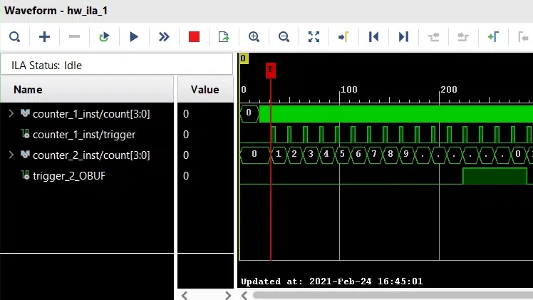
The waveform
Let’s examine the waveform to get an idea of what the testbench has been doing. The image below shows the waveform with the fill_count signal represented as an analog value. The FIFO is full when the trace for this signal is at the top, and empty when it’s at the bottom.
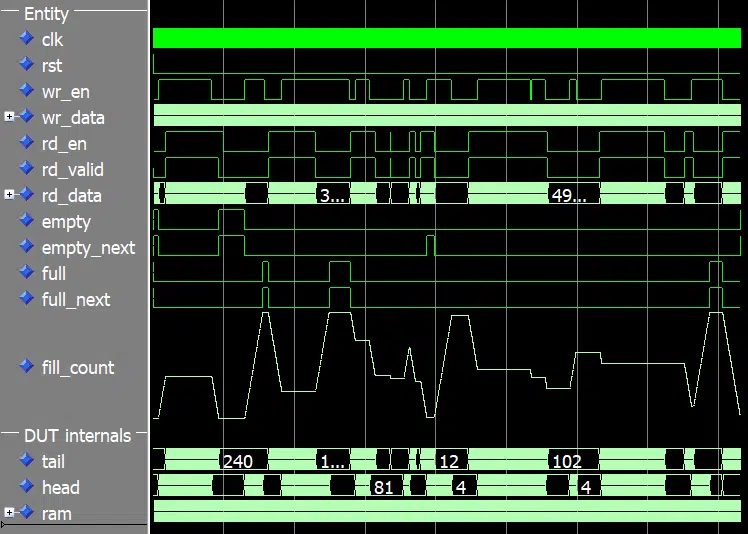
As we can see from the waveform, the ring buffer is being filled and emptied at random. Yet, we didn’t explicitly program these inclines and declines in fill level. Nevertheless, we are seeing an organic looking pattern of interaction with the DUT.
More about constrained random verification
Constrained random verification is a good testbench strategy when the test vector has too many permutations for an exhaustive test to be practical. The random interactions exhibit a more natural behavior than a directed corner case test would have done, without sacrificing accuracy.
We can be sure that all the corner cases have been met, as long as we have set up the coverage data collection correctly. The added benefit is that randomized testing is more likely to expose weaknesses in the DUT that you’re not specifically testing for. As long as you know of all the corner cases, you can create directed tests for them. But corner cases are easily overlooked, and that’s when you could benefit from the constrained random verification methodology.
This article has only scratched the surface of what you can do with constrained random verification. I recommend reading the docs at the OSVVM GitHub page to dig deeper into the subject.
I also recommend SynthWorks’ Advanced VHDL Testbenches and Verification course, which I am not affiliated with. However, I have attended the 5-day version of this physical course. The course is taught by Jim Lewis, the chair the VHDL Analysis and Standardization Group (VASG). Overall, a great investment for any company that wants to take their VHDL testbenches to the next level.
Need the Questa/ModelSim project files?
Let me send you a Zip with everything you need to get started in 30 seconds
Tested on Windows and Linux Loading Gif..


Hello Jonas,
I tried the FIFO you published, and I have different results for Modelsim and GHDL. On Modelsim 2020.1 the simulation ran sucessfully, but on GHDL (1.0.0 and 2.0.0-dev) it did not, ended with the following error:
❯ python run.py lib.ring_buffer_tb.all
Re-compile not needed
Starting lib.ring_buffer_tb.all
Output file: /home/user/src/fifo_vhlwhiz/vunit_out/test_output/lib.ring_buffer_tb.all_bda26499e73e205b42a79285e5027e57d0b32502/output.txt
0 fs – default – INFO – ———- Testbench started ———-
/home/user/src/fifo_vhlwhiz/sim/ring_buffer_tb.vhd:165:25:@1800ns:(report note): Push 62754
/home/user/src/fifo_vhlwhiz/sim/ring_buffer_tb.vhd:183:17:@1800ns:(assertion failure): empty=’1′ while fifo.IsEmpty=false
/home/user/src/fifo_vhlwhiz/vunit_out/test_output/lib.ring_buffer_tb.all_bda26499e73e205b42a79285e5027e57d0b32502/ghdl/ring_buffer_tb-rtl:error: assertion failed
in process .ring_buffer_tb(rtl).verify
/home/user/src/fifo_vhlwhiz/vunit_out/test_output/lib.ring_buffer_tb.all_bda26499e73e205b42a79285e5027e57d0b32502/ghdl/ring_buffer_tb-rtl:error: simulation failed
fail (P=0 S=0 F=1 T=1) lib.ring_buffer_tb.all (0.4 seconds)
I found it interesting, and so far, I could not figure out why it did happen. The only change I introduced was the VUnit in the testbench and the run.py file. You can find them in the following link:
https://gist.github.com/rafaelnp/52f1336bec84a4f0b1138b58d87e65ce
It would be interesting to know, if you can reproduce this error.
Best regards,
Rafael.
Hello, Rafael. I tried your code and got the same result. But I noticed that if I swap the order that the PROC_BEHAVIORAL_MODEL and PROC_VERIFY processes appear in the VHDL file, we get past that point, but it stops at another assertion failure later.
It behaves differently in GHDL than ModelSim because the execution order of protected type subprograms within the same delta cycles isn’t defined in the VHDL standard. It’s up to the VHDL simulator.
You found a weakness in my testbench.