I’m excited to announce that the VHDL and FPGA course that I have been working on for the last six months is starting to become complete. The course is in beta at the moment, and I am planning on launching it for the first time this autumn.
Who is the FPGA course for?
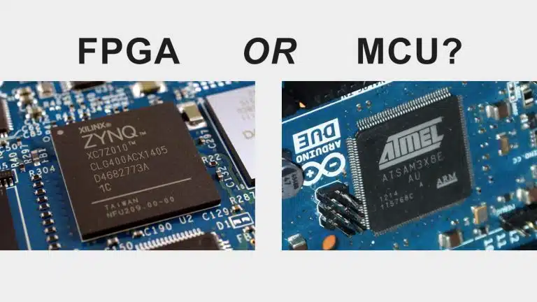
The FPGA course is intended for the developer who has knowledge of other programming languages but is new to VHDL and FPGAs. This course will take you from the beginner or intermediate level to being able to understand and use advanced VHDL coding constructs.
The course is perfect for the professional software engineer who has been tasked with FPGA development. It’s also suitable for students or freelancers who are interested in hardware design, perhaps contemplating a career transition to FPGA development.
Anyone with basic programming skills can benefit from the hands-on approach that this course teaches you. We are developing a real, physical product from scratch. I’m showing you exactly how I would have solved this problem if it was requested of me as an FPGA engineer.
The project

A dot matrix LED display controller is the product that we are creating in this course. Dot matrix LED displays are commonly used for large outdoor billboards or information displays these days. Although, they have been used for smaller devices such as digital watches and vending machines before the advent of inexpensive LCD displays.
You can do the course as a simulation-only exercise if you prefer to. You don’t need to purchase any hardware or even an FPGA development board. But you can create your own prototype if you want, all the information is included in the course.
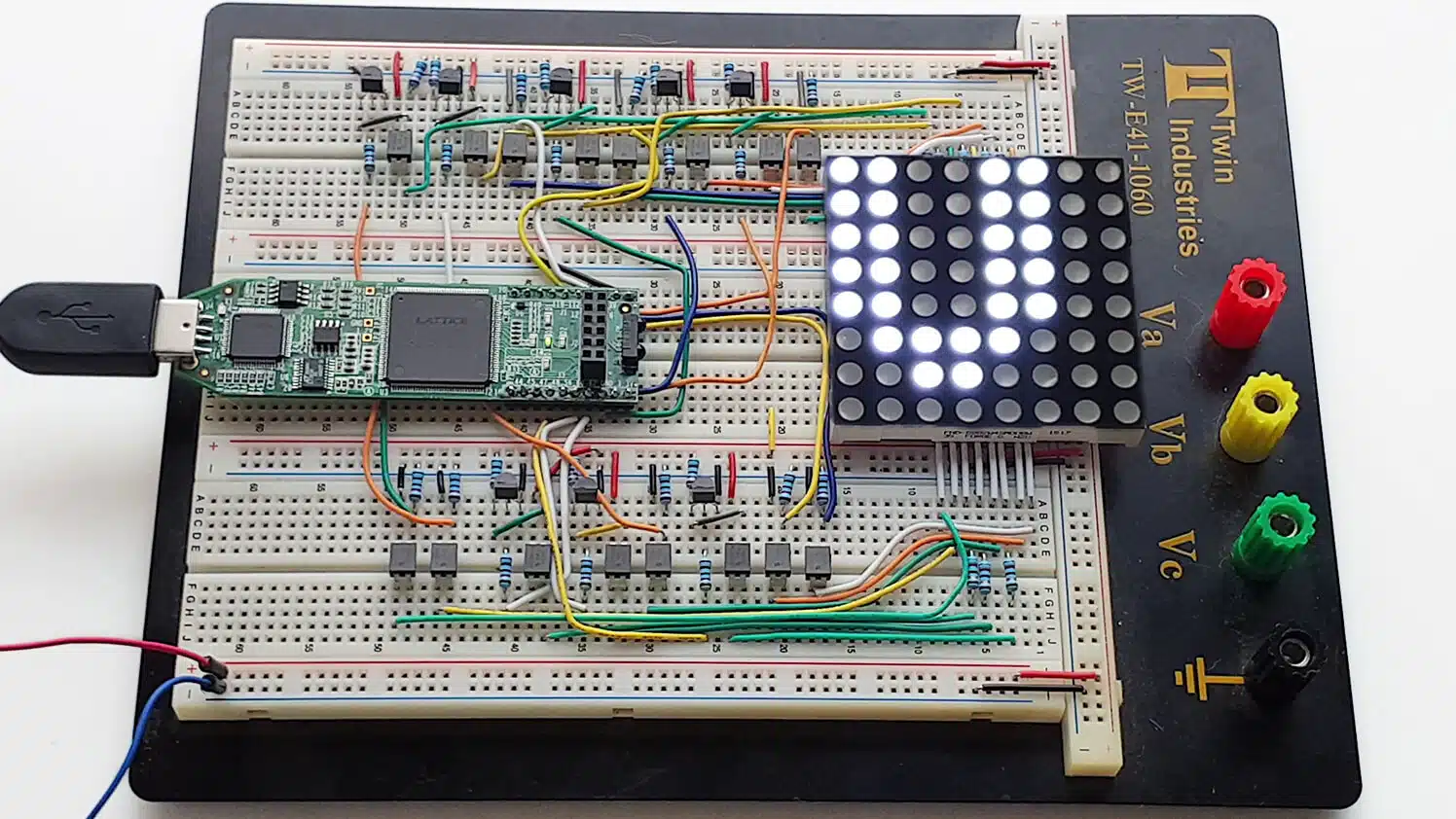
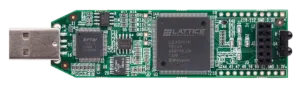
The Lattice iCEstick FPGA Evaluation Kit is the FPGA development board that’s used in this course. This $25 board features an iCE40 HX1K FPGA with 1280 logic elements and 64 kb of block RAM, which is more than enough for our application. The iCEstick board can be plugged directly into a breadboard, something that we’ll do when creating the prototype.
We create an FPGA implementation capable of controlling an 8×8 dot matrix LED display with 64 LEDs. The FPGA will store information in block RAM about how to render each ASCII character.
You will be able to send text to the FPGA by using the USB connector that’s present on the FPGA board. The text is rendered on the dot matrix display as we type in the serial terminal on the computer. The FPGA will echo the characters back to the serial terminal using the UART transceiver that we create in the course.

See the Bill of Materials (BOM) for all parts, consumables, and tools used for creating the prototype.
FPGA Course structure
The 120 lectures are divided into 17 sections, with videos lasting on average 10 minutes. I have intentionally split the complicated stuff into multiple shorter lectures to make it more manageable. Each section covers a VHDL module, a testbench, or a concept within VHDL and FPGA design. This course leaves nothing out, all concepts and design decisions are explained.
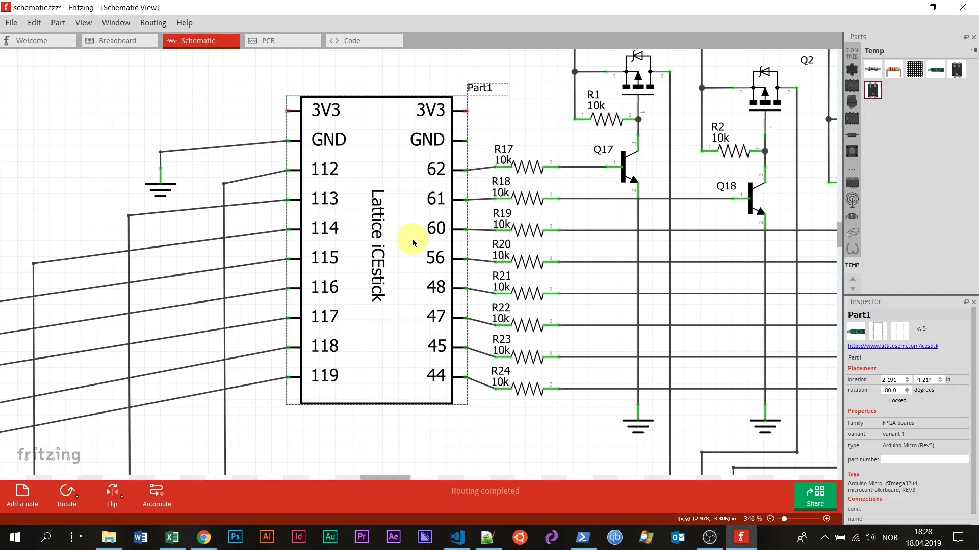
In the Getting started section, we install the required software and set up the development environment. The next section presents the Lattice iCEstick FPGA development board, as well as the analog schematic of the dot matrix display and the supporting circuit.
I will explain everything I do in the coding sessions so that you can follow the progress, even if you have only basic VHDL knowledge. You can relate the code that we write to any other programming language that you may know.
The Visual Studio Code (VSCode) editor with a VHDL plugin is used in this course. VSCode is one of the most popular programming editors at the moment, and it’s completely free of charge. We use the template snippets from the VHDL plugin to avoid spending time on trivial, repetitive code. Although, VSCode is not an IDE that completes code automatically without you really understanding what’s going on.

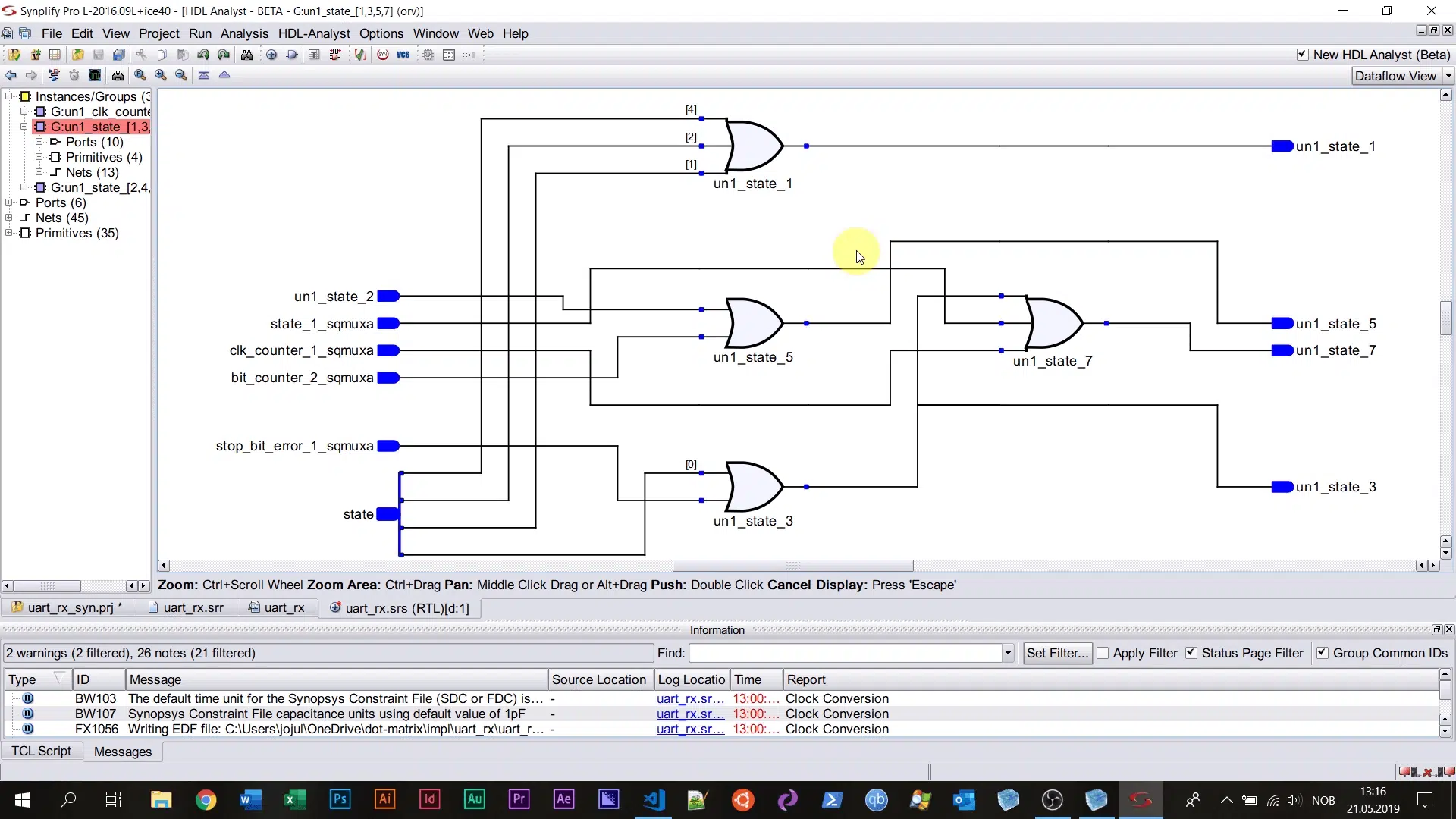
We synthesize every VHDL module individually and examine the schematic created by the synthesis tool. We do this as the last lecture of each coding section that produces an RTL (register-transfer level) production module. These lessons teach you valuable skills for understanding how each code line is translated into digital logic.
The Dot Matrix LED Controller FPGA course teaches you proper VHDL design techniques. Get it right the first time you power on the chip by creating a testbench for each module, at every design hierarchy. Trial and error is not a viable strategy when developing hardware. The course teaches you to develop self-checking testbenches as a professional FPGA engineer.
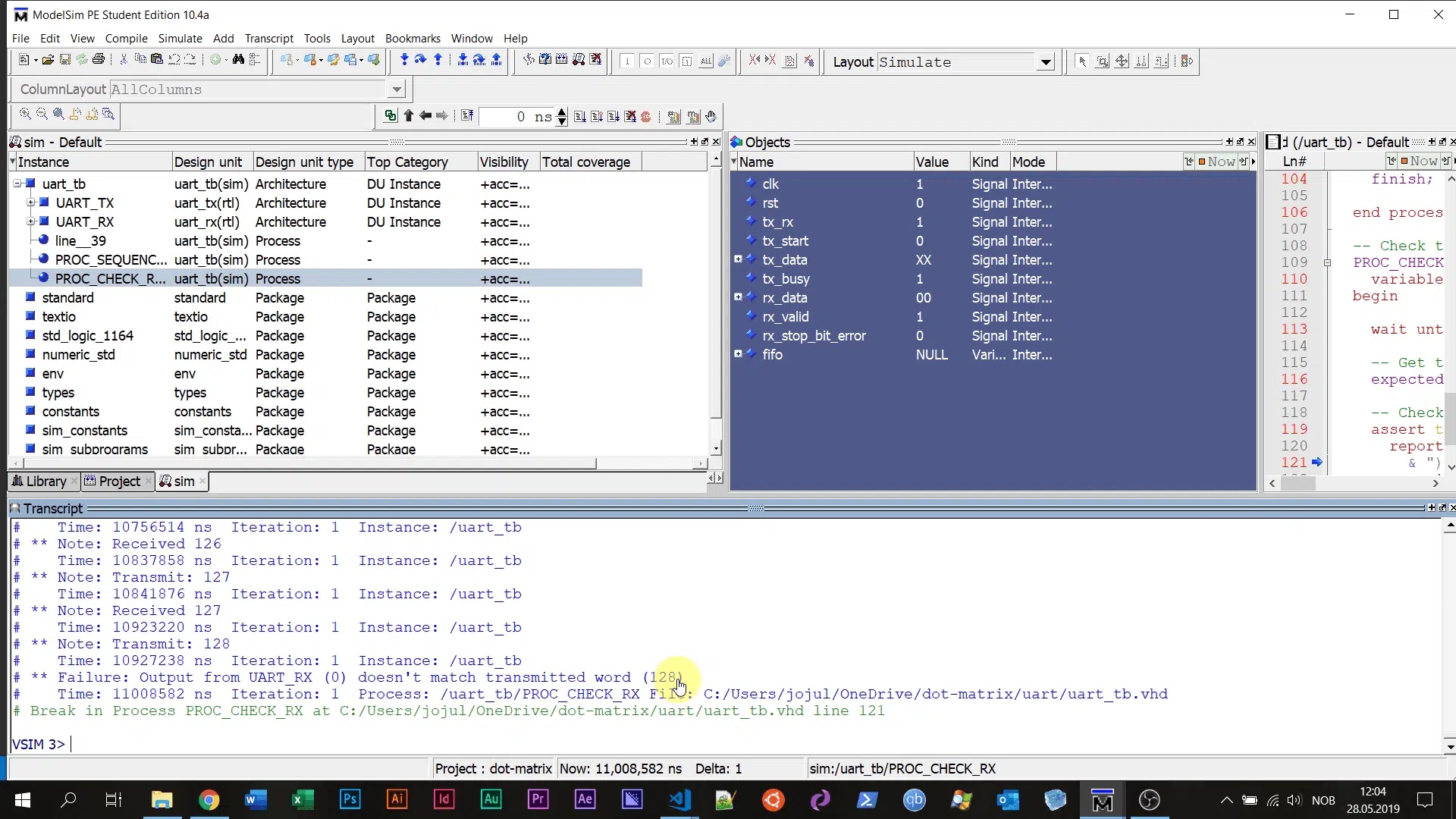
The ModelSim PE Student Edition is used in the course because it is the most commonly used VHDL simulator. The student edition of the simulator can be downloaded for free; this applies to all of the software used in this course.
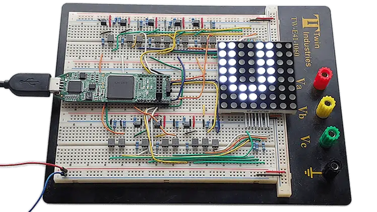
Finally, we wrap up the course by creating the physical prototype on the breadboard and implementing the design on the FPGA. The moment of truth is when we connect the device to the computer via the USB port and type in the serial terminal. Will the characters show up on the dot matrix LED display?
This is when the benefits of having a rigorous verification regime become apparent. The problems we have to deal with are a lot easier to solve than an unresponsive chip, which is the likely first outcome for a pure FPGA hobbyist project.
What you will learn from the FPGA course
You will learn how to approach a task as a professional FPGA engineer. The course will transform your VHDL skills to a level where you feel confident taking on any VHDL assignment.
These are some of the things that this course will teach you:
Advanced VHDL features
- Packages, records and subprograms
- Protected types (VHDL classes)
- Access types (VHDL pointers)
- Generics
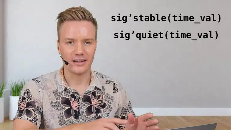
- Signal attributes like
'last_eventor'stable - VHDL-2008 features like hierarchical signal reference
Advanced testbench strategies
- Verification component
- Bus functional model
- Self-checking VHDL testbench
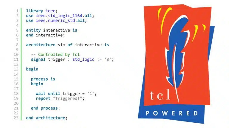
- Interactive TCL-driven testbench
Using FPGA design tools
- ModelSim VHDL simulator
- Synplify Pro synthesis software
- Lattice iCEcube2 design software
- Pin assignment and clock constraints
- Synthesis, place and route
Want to know more about the course?
Updated 21st of September 2019: I have completed the course.

Hi,
Would I be able to follow your course with different tools, like Xilinx Arty z7-20 board as development board and Vivado WebPack as integrated editor, simulator, synthesis tool?
How much will it cost?
Hi Igor,
I wouldn’t recommend using a different simulator or synthesis tool because they may behave slightly different, making it harder for you to follow the course. You won’t be able to follow my steps exactly. While the VHDL code should be portable, the TCL script uses a few commands that are specific to ModelSim.
Fortunately, the Lattice iCEcube2 FPGA software is easy to use, and you can request a free license for it. The student version of the ModelSim VHDL simulator can also be downloaded free of charge.
The Lattice iCEstick FPGA board that is used in the course costs only $25, to build the prototype you will have to source a number of parts. The cost depends on where you buy them from and if you have any parts and tools from before. You can have a look at the Bill of Materials (BOM) which lists all the parts, consumables, and tools that I used for building the prototype.
You may also do the course as a pure simulation course. We’re only going to touch physical hardware in the last of the 16 sections in the course, before that we’ll be working in software tools. By creating a proper testbench suite, you will see that we get very few surprises when we finally do program the FPGA.
The course will be priced at $247 with the option to split the payment over two months for $137 each.
Take a look at the course curriculum.
I wanted to know if the course would be paid or will have some charges?
Hi Navneet,
I’ve launched this course two times since I wrote this blog post. The price was $247 (USD) last time it was available for purchase. I haven’t decided on the price for future versions yet. You can always find up to date information about the next launch date on the Dot Matrix VHDL Course page.