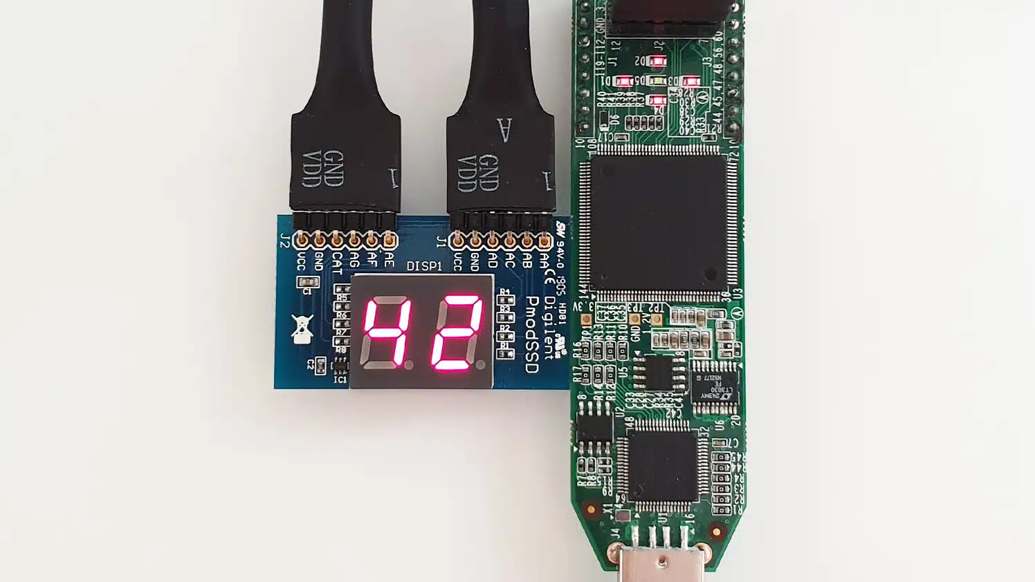
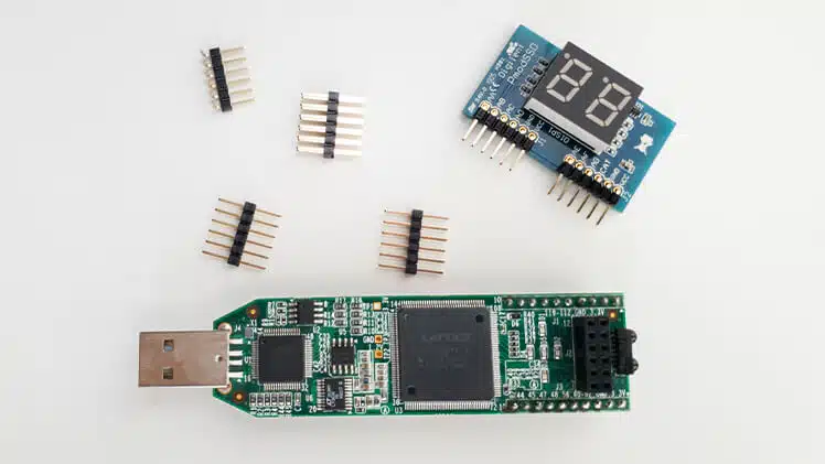
In this article, I will present a VHDL module that can display a two-digit number on the Pmod SSD: Seven-segment Display from Digilent. The dual 7-segment display is compatible with the Pmod interface, meaning that you can use it without any soldering. It fits into the Pmod connector, which is standard on many FPGA development boards.
To test the VHDL implementation, I’m using the Lattice iCEstick, a low-cost FPGA development board with a Pmod connector. In addition to the iCEstick, you need a 2×6-pin to Dual 6-pin Pmod Splitter Cable to convert from the parallel Pmod connector on the iCEstick to the in-series version of the plug that the 7-segment display expects. Finally, I recommend getting a USB type-A extension cable because plugging the iCEstick directly into the USB port on the computer is impractical.
How 7-segment displays work
There are many different 7-segment displays on the market. The number of digits varies between them, and so does the physical interface and pinout. A generic solution that covers all possible 7-segment displays that you may encounter probably wouldn’t be very user-friendly. However, you can use the code presented in this article as a basis and modify it to suit your needs.
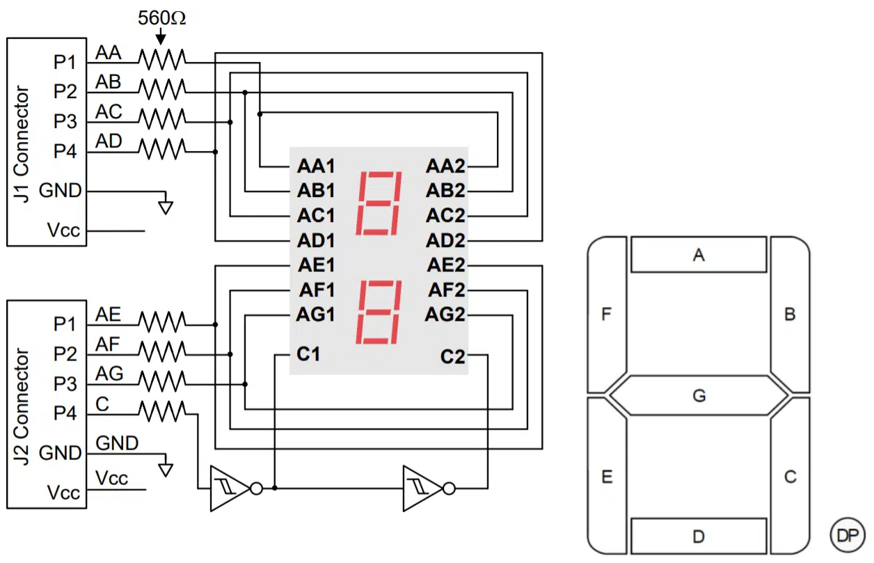
The image above is from the datasheet for the Digilent Pmod module. It shows how the 7-segment display connects to the Pmod pins. These pins are directly accessible to the FPGA on the iCEstick.
Seven of the pins control one segment each on the display. By driving a logic high value on such a pin, the corresponding segment will illuminate on the display. But there are two digits on this display, and we can only control one at the time. The P4/C pin on the J2 connector selects one or the other digit. When the logic voltage on this pin is '0', the right digit illuminates, if it’s '1', the left digit is activated.
The “DP” decimal point is unconnected and cannot be accessed.
The entity
The code below shows the entity of our seg7 VHDL module. The entity has a generic port with a constant named clk_cnt_bits. It defines the length of an internal counter that controls the refresh rate of the display, the frequency of alternating between the left and right digits.
The exact frequency is not essential. Select a counter length that lies in the range from 50 to a couple of hundred Hertz. The formula that determines the refresh rate is refresh_hz = 2clk_cnt_bits / clk_hz.
entity seg7 is
  generic (
    -- refresh_hz = (2 ** clk_cnt_bits) / clk_hz
    clk_cnt_bits : integer
  );
  port (
    clk : in std_logic;
    rst : in std_logic;
    value : in integer range 0 to 99;
    segments : out std_logic_vector(6 downto 0);
    digit_sel : out std_logic
  );
end seg7;
In addition to the clock and reset, the entity has one input signal: the value to display on the 7-segment display. The value signal is an integer type restricted to the range 0 to 99 because these are the only number values it’s possible to show using only two digits.
The output signals are the seven segments as a vector and the digit selector signal for picking either the left or the right digit to illuminate.
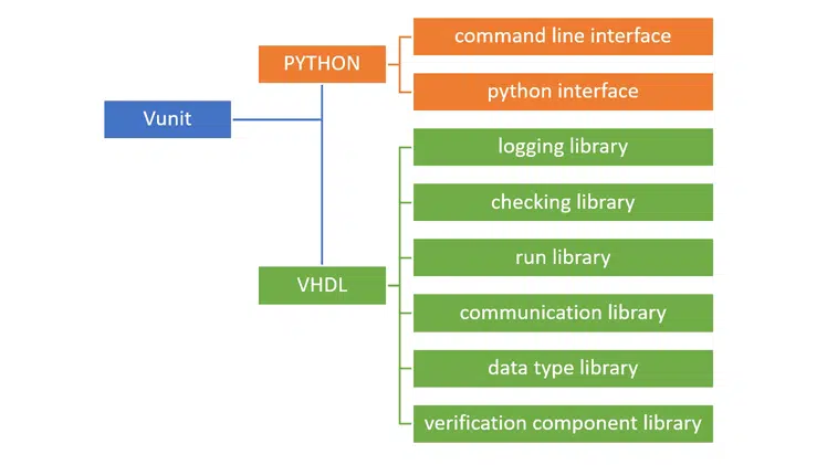
Need the Questa/ModelSim project files?
Let me send you a Zip with everything you need to get started in 30 seconds
Tested on Windows and Linux Loading Gif.. 
Representing a binary-coded decimal
To represent the digits shown on the display we will use the format known as binary-coded decimal (BCD). While a binary representation is the most efficient way to store the decimal number, we run into problems when trying to split it into the left and right digit to show on the display. We can’t distinguish between the decimal digits merely by slicing the vector used to store the number.
subtype digit_type is integer range 0 to 9;
type digits_type is array (1 downto 0) of digit_type;
signal digit : digit_type;
signal digits : digits_type;
As shown in the code above, we declare a subtype of the integer on the range 0 to 9 for describing the value that can be represented by one decimal digit. Then, we declare a new array type that can hold two such BCD values. The digit signal holds the number currently being shown on either the left or right side of the display. On the other hand, the digits signal contains the individual decimal characters for the two digits, as they will appear to a person viewing the screen.
Convert decimal to BCD
The input to this module, value, is an integer on the range 0 to 99, a binary representation of the number. We need to convert this single integer to two integers on the range 0 to 9, the BCDs.
The standard algorithm for this is Double Dabble, also known as the shift-and-add-3 algorithm. While this is fine to use, I will opt for a shorter solution in our case because we only have two digits to separate.
digits(1) <= value / 10;
digits(0) <= value - ((value / 10) * 10);
By using integer division as shown in the code above, we can isolate the most significate decimal digit and assign it to the digits(1) signal. To fetch the least significant digit, we can subtract the most significant digit from the value signal, leaving us with only the number to assign to the digits(0) signal.
Counting clock cycles
Delaying time in FPGAs is simply a matter of counting clock cycles. The clock period is the only predictable time interval that you can rely on in your VHDL code. The code below shows the clk_count signal, which we are using for counting clock cycles. The clk_cnt_bits generic determines how many bits to reserve for this unsigned signal.
signal clk_cnt : unsigned(clk_cnt_bits - 1 downto 0);
The exact refresh rate of the display is of less importance, that’s why I’ve opted for an unsigned type here. It allows us to utilize the self-wrapping behavior of the unsigned signal. All we have to do is to increment the counter on every rising edge of the clock. The code below shows the synchronous process with reset that takes care of this.
COUNT_PROC : process(clk)
begin
  if rising_edge(clk) then
    if rst = '1' then
      clk_cnt <= (others => '0');

    else
      clk_cnt <= clk_cnt + 1;

    end if;
  end if;
end process;
Alternate between digits
Now that we have the free-running counter working, we can use the most significant bit (MSB) of the unsigned counter signal to switch between the two digits. The MSB alternates between '0' and '1' with a 50% duty cycle. The first line of the code below sets the digit_sel signal based on the value of the MSB. The second line implements a multiplexer with the MSB used as the selector. It will forward the value of the active digit from the digits array to the digit signal.
digit_sel <= clk_cnt(clk_cnt'high);
digit <= digits(0) when clk_cnt(clk_cnt'high) = '0' else digits(1);
BCD to 7-segment encoder
The final step of the seg7 module is to translate the BCD stored in the digit signal to a visual representation on the 7-segment display. The code below shows a process that achieves this by using a case-statement.
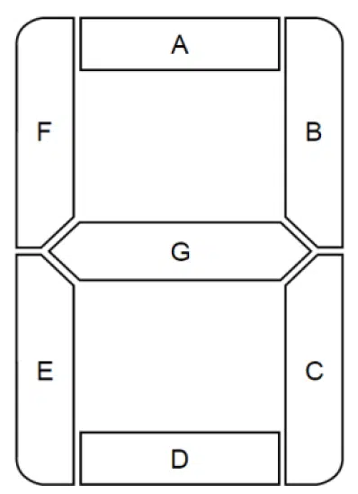
The position in the vector of each bit literal corresponds to one segment on the display. Index 0 equals segment A, index 1 is B, and so on, all the way to index 6, which controls segment G. The mappings of segments to vector indexes are derived from the datasheet for the Digilent 7-segment display.
ENCODER_PROC : process(digit)
begin
  case digit is

    when 0 => segments <= "0111111";
    when 1 => segments <= "0000110";
    when 2 => segments <= "1011011";
    when 3 => segments <= "1001111";
    when 4 => segments <= "1100110";
    when 5 => segments <= "1101101";
    when 6 => segments <= "1111101";
    when 7 => segments <= "0000111";
    when 8 => segments <= "1111111";
    when 9 => segments <= "1101111";

    end case;
end process;
The output
The seg7 VHDL module will render on the display whatever you assign to the value input signal. In the testbench, we increment the value signal once every second. Then, we simulate a little more than 100 seconds so that we can observe the wrapping point of the value counter.
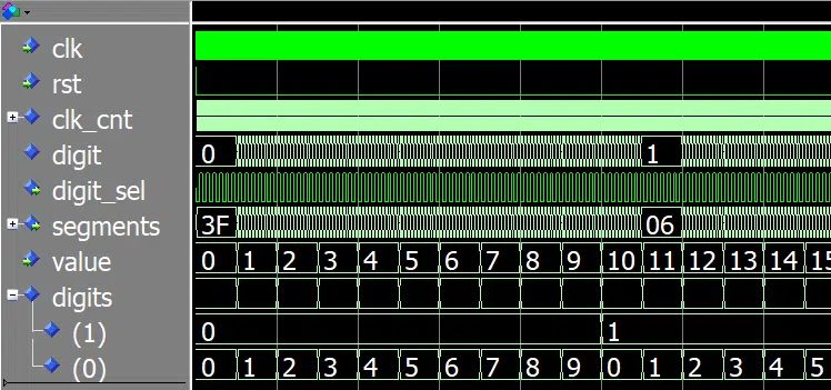
The waveform above is from ModelSim. It shows the first part of the simulation, where the value has counted from 0 to 15. We can see that the numbers in the digits array are counting as well. The ones (0) are counting every time the value signal changes, while the tens (1) increment on every tenth number.
You can download the ModelSim project, including the testbench, by using the form below.
Need the Questa/ModelSim project files?
Let me send you a Zip with everything you need to get started in 30 seconds
Tested on Windows and Linux Loading Gif..
If you implement the seg7 module as the top module on the FPGA, the display will most likely show a stable “00”. That’s because '0' is the most common default value given to uninitialized signals in FPGAs. When the value signal gets set to all zeros, the display will show just that.
To cycle through all possible input numbers, I created a wrapper VHDL module that increments the value signal ten times per second. I then instantiated the seg7 module in the wrapper before I implemented the design on the Lattice iCEstick. The looping Gif video below shows how the implemented design looks on the 7-segment display.

Buying the Pmod SSD: Seven-segment Display
The 7-segment display used in this blog post comes from Digilent. You can purchase the Pmod module from the Digilent webshop, or you can get it from one of the many resellers. In the listing below, I have linked to the product page for the display in a few online electronics stores that carry the item.
- Digilent
- Digi-Key
- Mouser
- RS Electronics (UK)
(Go to the RS Electronics main page to select the site for your country) - Farnell (UK)
(Go to the Farnell main page to select the site for your country)
Please note that if you want to use the Digilent 7-segment display with the Lattice iCEstick, or any other FPGA development board that has a 6×2-pin Pmod connector, you also need a splitter cable. The cable is available from Digilent, Digi-key, Mouser, and RS Electronics.
Additionally, all the components are available from various sellers on Amazon and eBay.
VHDL course using the Digilent 7-segment display
I’ve launched a new VHDL and FPGA course for absolute beginners. In the course, I use the 7-segment display from Digilent and the Lattice iCEstick FPGA development board for teaching VHDL. Click the link below to read more about the course!
Are you familiar with programming but new to VHDL?
Do you need a short introduction to this unfamiliar subject?
Is your schedule full with no time left to study?
Understand the basics of FPGA development using VHDL in a few evenings! This course is for IT professionals and students who need a fast run-down of the subject. With this course and the low-cost Lattice iCEstick development board, you will be developing real hardware within hours.
Click here to read more and enroll:
FPGA and VHDL Fast-Track: Hands-On for Absolute Beginners


Hi,
Great tutorial Jonas! thanks for sharing. I’ve got one curiosity, once you are happy with your code and simulation, what IDE/tools do you use to create and download the FPGA programming file?
Thanks ?.
To implement the code on the iCEstick FPGA development board, I used iCEcube2, the FPGA design software from Lattice. In iCEcube2, I imported the VHDL files and assigned physical pins to the entity signals.
Then, after generating the bitmap (programming file), I used the Diamond Programmer tool to configure the FPGA using USB. The Diamond Programmer tool ships with the iCEcube2 installer.
The screenshots below are from the FPGA and VHDL Fast-Track course, which I’m going to launch shortly.
Lattice iCEcube2
https://vhdlwhiz.com/wp-content/uploads/2020/01/icecube2.jpg
Lattice Diamond Programmer
https://vhdlwhiz.com/wp-content/uploads/2020/01/diamond-programmer.jpg
Hi Jonas, thank you so much for the tutorials, their are very helpful.
I some problems with 7 segment display.
I implemented the timer and I would like to show the time with the 7 segment display, so I divided the bit in most and less significant, but the display shows the time with a delay of 2 data updates, for examples if the time is 8 second, the 7 segment display shows 6 second, or if the time is 3 hours it shows 1 hours, and it will update the time at 2 hours when the bit for 4 hours arrive.
How can I manage this delay?
Thank you so much for the helping.
Hello Michele,
It’s nice to hear from you!
I couldn’t figure out what’s wrong only based on the symptoms that you are describing. I would have to see a code example to understand more. Perhaps you can post the question in my private Facebook group where we can discuss the problem more easily.
Thank you so much Jonas.
Hi,
Thanks for the tutorial! I’m relatively new to VHDL so i was wondering if you could explain how the arithmetic for digits(0) solves for the LSB? Is it just dividing the value by 10 then multiplying it by 10 ? If so, how does this do anything to solve for the LSB?
Hello Ross, nice to hear from you!
I’m exploiting how integer division works to get rid of the fractional part of the number.
Let’s pretend all objects were variables so that we can break down the calculation:
The involved signals are of integer type and, therefore, cannot hold any fractional numbers. The fractional component is discarded, in effect, rounding down the result to the nearest integer.
Ah, I see now, thats really clever!
Thank you so much, this tutorial has been a massive help for my university project so really appreciate the quick reply and the help!