The std_logic_vector type can be used for creating signal buses in VHDL. The std_logic is the most commonly used type in VHDL, and the std_logic_vector is the array version of it.
While the std_logic is great for modeling the value that can be carried by a single wire, it’s not very practical for implementing collections of wires going to or from components. The std_logic_vector is a composite type, which means that it’s a collection of subelements. Signals or variables of the std_logic_vector type can contain an arbitrary number of std_logic elements.
This blog post is part of the Basic VHDL Tutorials series.
The syntax for declaring std_logic_vector signals is:
signal <name> : std_logic_vector(<lsb> to <msb>) := <initial_value>;or
signal <name> : std_logic_vector(<msb> downto <lsb>) := <initial_value>;where <name> is an arbitrary name for the signal and <initial_value> is an optional initial value. The <lsb> is the index of the least significant bit, and <msb> is the index of the most significant bit.
The to or downto specifies the direction of the range of the bus, basically its endianness. Although both work equally well, it’s most common for VHDL designers to declare vectors using downto. Therefore, I recommend that you always use downto when you declare bit vectors to avoid confusion.
The VHDL code for declaring a vector signal that can hold a byte:
signal MySlv : std_logic_vector(7 downto 0);
The VHDL code for declaring a vector signal that can hold one bit:
signal MySlv : std_logic_vector(0 downto 0);
The VHDL code for declaring a vector signal that can hold zero bits (an empty range):
signal MySlv : std_logic_vector(-1 downto 0);
Exercise
In this video tutorial, we will learn how to declare std_logic_vector signals and give them initial values. We also learn how to iterate over the bits in a vector using a For-Loop to create a shift register:
The final code we created in this tutorial:
library ieee;
use ieee.std_logic_1164.all;

entity T11_StdLogicVectorTb is
end entity;

architecture sim of T11_StdLogicVectorTb is

    signal Slv1 : std_logic_vector(7 downto 0);
    signal Slv2 : std_logic_vector(7 downto 0) := (others => '0');
    signal Slv3 : std_logic_vector(7 downto 0) := (others => '1');
    signal Slv4 : std_logic_vector(7 downto 0) := x"AA";
    signal Slv5 : std_logic_vector(0 to 7)     := "10101010";
    signal Slv6 : std_logic_vector(7 downto 0) := "00000001";

begin

    -- Shift register
    process is
    begin

        wait for 10 ns;

        for i in Slv6'left downto Slv6'right + 1 loop
            Slv6(i) <= Slv6(i-1);
        end loop;

        Slv6(Slv6'right) <= Slv6(Slv6'left);

    end process;

end architecture;
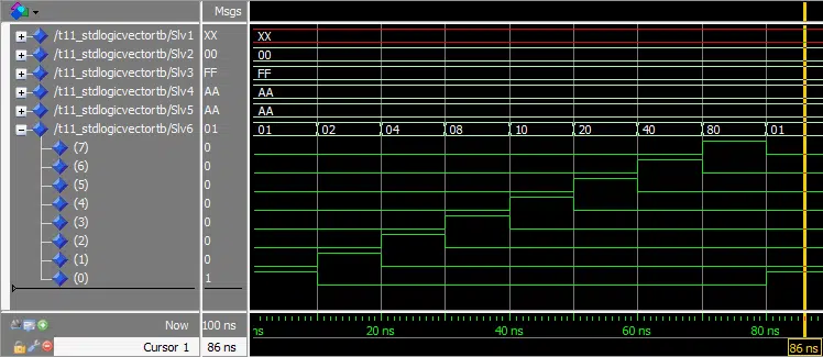
The waveform window in ModelSim after we pressed run, and zoomed in on the timeline:
Need the Questa/ModelSim project files?
Let me send you a Zip with everything you need to get started in 30 seconds
Tested on Windows and Linux Loading Gif.. 
Analysis
In this exercise we declared six std_logic_vector buses, each eight bits long (one byte).
Signal Slv1 was declared without a initial value. The bus is seen having the value XX in the waveform screenshot. This is because the value that is displayed on the bus is in hexadecimals, and XX indicates a non-hex value. But when we expanded the bus in the waveform, we could see that the individual bits were indeed U’s.
Signal Slv2 was declared using an initial value of all 0’s. Instead of specifying the exact value for each bit, we used (other => '0') in place of the initial value. This is known as an aggregate assignment. The important part is that it will set all bits in the vector to whatever you specify, no matter how long it is.
Signal Slv3 was declared using an aggregate assignment to give all bits the initial value of 1. We can see FF displayed on this signal in the waveform, which is hex for eight 1’s.
Signal Slv4 was declared with an initial value specified in hex, AA. Each hex digit is 4 bits long, therefore we must supply two digits (AA) for our vector which is 8 bits long.
Signal Slv5 declares exactly the same initial value as Slv4, but now we specified it as the binary value 10101010. We can see from the waveform that both signals have the hex value AA.
Signal Slv6 was declared with an initial value of all zeros, except for the rightmost bit which was '1'. We used a process to create a shift register from this signal. The shift register, as the name implies, shifts the contents of the vector one place to the left every 10 nanoseconds.
Our process wakes up every 10 ns, and the For-Loop shifts all bits in the vector one place to the left. The final bit is shifted back into the first index by the Slv6(Slv6'right) <= Slv6(Slv6'left); statement. In the waveform we can see the '1' ripple through the vector.
This is a visualization of how the '1' propagates through our shift register:
By using the 'left' and 'right attributes, we made our code more generic. If we change the width of Sig6, the process will still work. It’s good design practice to use attributes where you can instead of hardcoding values.
You may be wondering if there are more attributes that you can use, and there are. I won’t be talking more about them in this tutorial series, because I consider them to be advanced VHDL features.
Get free access to the Basic VHDL Course
Download the course material and get started.
You will receive a Zip with exercises for the 23 video lessons as VHDL files where you fill in the blanks, code answers, and a link to the course.
By submitting, you consent to receive marketing emails from VHDLwhiz (unsubscribe anytime).
Takeaway
- N-bit vectors should be declared using
std_logic_vector(N-1 downto 0) - A vector can be assigned as a whole or bits within it can be accessed individually
- All bits in a vector can be zeroed by using the aggregate assignment
(others => '0') - Code can be made more generic by using attributes like
'leftand'right
Take the Basic VHDL Quiz – part 2 »
or
Go to the next tutorial »


Hi! Excellent article. I have a question, why would you ever use std_logic_vector(0 downto 0) instead of just std_logic?
Thanks!
Hi Derek,
I have seen
std_logic_vector(0 downto 0)being used for mapping astd_logicto a module that has a vector with generic width as an input. Consider this port declaration:If we want to use a
std_logicas input here, we need to first convert it to astd_logic_vector.In deep logic where generics are used, you may also encounter the zero-width bus. That is, when generics causes a bus to evaluate to this:
std_logic_vector(-1 downto 0). It is legal, but it is also a source of synthesis warnings. For example this warning message from Vivado:"WARNING: [Synth 8-3919] null assignment ignored"Hey, I would like to thank you for these tutorials, it not easy to find short and well-explained VHDL lessons nowadays.
I’m glad you found the tutorials helpful. Stay tuned for more advanced topics about VHDL on the blog in the upcoming weeks and months.
Hi sir,
i want to take values to array of bit vector from my input bit stream how can i assign? i can not do it by slicing of my array and assigning input value. then how can i do the same
Hi Archana,
To deserialize data that is arriving over a one-bit interface, you can clock the data into a shift register like I’m doing in this blog post. Read out the data word (or byte) when the shift register is full.
The other method is to assign the received bits directly to the correct index in the receive buffer.
Either way, you will have to count the number of received bits to keep track of the position within the received word. You should implement a simple state machine with a counter to take care of this.
Thank you sir..
I have a signal of type “” type ram is array( 0 to 15) of bit_vector(3 down to 0);”” and i have to read elements from text file to this . how can i do this? i am using Textio library. now i am doing it by creating individual 16 signals of bit_vector(3 down to 0) and read the file text to this from the variable and then assigning four such signal to input of type ram is array( 0 to 15) of bit_vector(3 down to 0);
like,
read(v_1LINE,input);

a1<=input(1 to 4);
a2<=input(5 to 8);
a3<=input(9 to 12);
a4<=input(13 to 16);
indata1<=(a1,a2,a3,a4);
how can i do the same by avoiding these steps?
Oh, I see. You want to initialize a RAM from a text file. In the example below, I am initializing your RAM in the declarative region of the VHDL file by using an impure function.
  type ram is array(0 to 15) of bit_vector(3 downto 0);

  impure function init_ram return ram is
    file v_file : text open read_mode is "data.txt";
    variable v_1LINE : line;
    variable v_value : bit_vector(3 downto 0);
    variable v_ram : ram;
  begin

    readline(v_file, v_1LINE);

    --for i in ram'range loop -- To fill the whole RAM
    for i in 0 to 3 loop -- To fill the first 4 elements
      read(v_1LINE, v_value);
      v_ram(i) := v_value;
    end loop;

    return v_ram;
  end function;

  signal indata1 : ram := init_ram;
I’ve used your types and signal names. First, we declare the type. Then, we declare an impure function which reads the bits from the data.txt file. Finally, we use the return value from the function as an initial value for the indata1 RAM signal.
Thank You Sir.
I would also like to say that your website has been very helpful! Thanks for all of your efforts on the website and also for any input on my question below, if you have time.
Is it possible to create a port with mixed inputs and outputs other than using inout? That generates a lot of warnings which doesn’t hurt anything however I usually try to avoid warning.
Hello Steve,
A common way to handle this is to declare a local copy of the output signal. Look at the example below to see what I mean.
entity ent1 is port ( sig1 : out std_logic ); end ent1; architecture rtl of ent1 is signal sig1_i : std_logic; begin sig1 <= sig1_i -- Use only sig1_i internally in this VHDL file end architecture;Thanks for your reply!
I was hoping to have a single “Bus name” in the entity port list with some of the signals in the bus being inputs and others being outputs.
I might be misinterpreting your response or my question might not be clear. Either way, thanks for your time and if you have any additional suggestions, feel free to post them but if not, no worries. Warnings really don’t matter but I prefer to avoid them.
For example:
– CPLD_B2:26 – CPLD_B2:01 are dedicated outputs
– CPLD_B2:27 is a dedicated input.
I can assign them “inout” but warnings are generated as follows:
Following 27 pins have no output enable or a GND or VCC output enable
Info (169065): Pin CPLD_B2[1] has a permanently enabled output enable File.
Oh, I see. That’s only possible in VHDL-2019. Unfortunately, not all FPGA tools support the newest VHDL revision yet. You can read about the change here:
https://vhdlwhiz.com/vhdl-2019/#interfaces
Thanks and keep up the great website!
Could you shed some light on toggling multiple bits in a logic vector at the same time?
Hello Sankalp,
You can use a For loop to flip every bit in the vector:
Hey Jonas,
Would this vhdl code be on an infinite loop? Continuously shifting the 1 left?
Hello Jareb,
I wouldn’t consider the shift register process to be an infinite loop because there is a
wait for 10 ns;statement inside of it. But I guess from a software perspective, it is an infinite loop because it never stops.After the simulator executes the last line of a process without a sensitivity list, it immediately continues from the first line again. That’s why we always need to have a Wait statement inside of the process, or we have to use a sensitivity list.
Try to remove the Wait statement from the process and simulate! You will see ModelSim complaining because it’s an infinite loop that continues without any time passing.
Hello, I don’t get the logic behind the last statement. When I work it around on paper it doesn’t seem to work to me..
Every 10 nanoseconds you shift right, let’s start with an easy one : 0010
First iteration :
for loop => 0100
shift left bit into right bit => 0100
Second iteration :
for loop => 1000
shift left to right => 1001
And by the end of the 10 nanoseconds, you don’t have the right shifting format.. A ‘1’ was added.
If you have an explanation, I take it. Cheers !
It may be that you are confused by the order of events in this code:
for i in Slv6'left downto Slv6'right + 1 loop
    Slv6(i) <= Slv6(i-1);
end loop;

Slv6(Slv6'right) <= Slv6(Slv6'left);
If I move the last line above the For loop like this:
Slv6(Slv6'right) <= Slv6(Slv6'left);

for i in Slv6'left downto Slv6'right + 1 loop
    Slv6(i) <= Slv6(i-1);
end loop;
That will actually make no difference (try it!). Because when you assign to a signal in VHDL, you schedule a value onto that signal in the future, in the next time step.
Thus, all the signal assignments in the For loop, as well as the feedback assignment, happen at the same time. They all change when the process restarts and hits this line:
So, there will only be one ‘1’ in the shift reg at a time.
Alright, thanks for the explanation !