The most common type used in VHDL is the std_logic. Think of this type as a single bit, the digital information carried by a single physical wire. The std_logic gives us a more fine-grained control over the resources in our design than the integer type, which we have been using in the previous tutorials.
Normally, we want a wire in a digital interface to have either the value '1' or '0'. These two values are the only values that a bit, a binary digit, can have. But in reality, a physical digital signal can be in a number of states, which the std_logic type does a good job emulating. Therefore it is the most frequently used type in VHDL.
This blog post is part of the Basic VHDL Tutorials series.
The std_logic type can have the following values:
| ‘1’ | Logic 1 |
| ‘0’ | Logic 0 |
| ‘Z’ | High impedance |
| ‘W’ | Weak signal, can’t tell if 0 or 1 |
| ‘L’ | Weak 0, pulldown |
| ‘H’ | Weak 1, pullup |
| ‘-‘ | Don’t care |
| ‘U’ | Uninitialized |
| ‘X’ | Unknown, multiple drivers |
This may seem like a lot of different states for a type that is supposed to model a single binary value. Don’t worry, we won’t be using all these types in this tutorial series. We will be using '1' and '0' of course. And we will also be seeing 'U' and 'X', which will help us spot errors in our design. The other values are advanced VHDL features which can be used for things like modeling communication with for example I2C devices, or for creating tri-state buses.
If several processes are trying to write different values to a signal, we say that it has multiple drivers. If a std_logic signal has multiple drivers, it won’t be a compilation or run-time error, at least not in the simulator. That is because std_logic is a resolved type, meaning that its value will be determined by a resolution function.
The value of a std_logic signal with two drivers will be determined based on this resolution table:
| U | X | 0 | 1 | Z | W | L | H | – | |
|---|---|---|---|---|---|---|---|---|---|
| U | X | X | 1 | 1 | 1 | 1 | 1 | X | 1 |
| U | X | 0 | X | 0 | 0 | 0 | 0 | X | 0 |
| U | U | U | U | U | U | U | U | U | U |
| U | X | X | X | X | X | X | X | X | X |
| U | X | 0 | 1 | Z | W | L | H | X | Z |
| U | X | 0 | 1 | W | W | W | W | X | W |
| U | X | 0 | 1 | L | W | L | W | X | L |
| U | X | 0 | 1 | H | W | W | H | X | H |
| U | X | X | X | X | X | X | X | X | – |
Exercise
In this video tutorial we will learn how to use declare and show std_logic signals in a waveform:
The final code we created in this tutorial:
library ieee;
use ieee.std_logic_1164.all;

entity T10_StdLogicTb is
end entity;

architecture sim of T10_StdLogicTb is

    signal Signal1 : std_logic := '0';
    signal Signal2 : std_logic;
    signal Signal3 : std_logic;

begin

    process is
    begin

        wait for 10 ns;
        Signal1 <= not Signal1;

    end process;

    -- Driver A
    process is
    begin

        Signal2 <= 'Z';
        Signal3 <= '0';
        wait;

    end process;

    -- Driver B
    process(Signal1) is
    begin

        if Signal1 = '0' then
            Signal2 <= 'Z';
            Signal3 <= 'Z';
        else
            Signal2 <= '1';
            Signal3 <= '1';
        end if;

    end process;

end architecture;
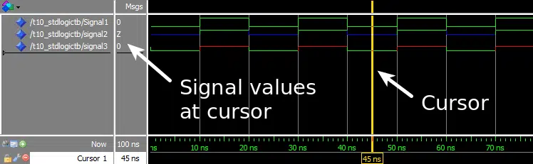
The waveform window in ModelSim after we pressed run and zoomed in on the timeline:
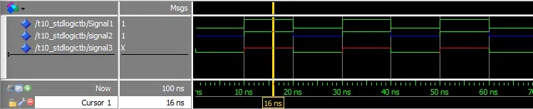
The waveform with the cursor placed on the other part of the repeating signal cycle:
Need the Questa/ModelSim project files?
Let me send you a Zip with everything you need to get started in 30 seconds
Tested on Windows and Linux Loading Gif.. 
Analysis
The exercise demonstrated how the resolution function of VHDL works with the std_logic type. When working with digital logic it’s often more practical to study the timeline in a waveform rather than using printouts. Therefore we used the ModelSim waveform to check the signal values in this exercise.
The first process and Signal1 is only used for changing the value that the third process is driving on Signal2 and Signal3.
The second process, Driver A, will try to drive a 'Z' onto Signal2, and a '0' onto Signal3 constantly.
The third process, Driver B, will alternate between driving '1' and 'Z' onto both Signal2 and Signal3.
We see in the waveform screenshots that Signal1 is changing between '0' and '1', because there is only one process trying to drive this signal. We can also see that the multiple driver signals are resolved according to the resolution table posted in the VHDL code comments:
| Signal | Driver A | Driver B | Result |
|---|---|---|---|
| Signal2 | ‘Z’ | ‘Z’ | ‘Z’ |
| Signal2 | ‘Z’ | ‘1’ | ‘1’ |
| Signal3 | ‘0’ | ‘Z’ | ‘0’ |
| Signal3 | ‘0’ | ‘1’ | ‘X’ |
Get free access to the Basic VHDL Course
Download the course material and get started.
You will receive a Zip with exercises for the 23 video lessons as VHDL files where you fill in the blanks, code answers, and a link to the course.
By submitting, you consent to receive marketing emails from VHDLwhiz (unsubscribe anytime).
Takeaway
std_logicis the most common type used to hold a single bit value in VHDL- Think of a
std_logicsignal as a physical wire in our digital design - If multiple processes try to drive a
std_logicsignal, its value is determined by a resolution table

@Jonas
Thank you for the tutorial.
I understand why, when there is a double assignment for Signal3, such as ‘0’ from Driver A and ‘1’ from Driver B, the resolution table forces signal3 to ‘X’.
I understand why signal3 is assigned to ‘0’ in Driver A during the first pass, but I wonder why signal3 is assigned to ‘0’ after this first execution. Since there is a final wait instruction at the end of Driver A process, which I thought means that this process hangs there for ever, doesn’t this mean that after the first assignment to ‘0’, Driver A process never executes again, meaning never assigns ‘0’ to Signal3 again? And there is in fact only one single assignment for Siganl3, in Driver B, for the rest of the execution?
Hi Kana,
Driver A will continue to drive the value ‘0’ onto Signal3 as long as it is paused at the Wait statement. Event though the process is now paused forever, it is still active in the sense that it will continue to drive those values forever.
If we wanted Driver A to stop driving Signal3 at some point, we should assign ‘Z’ to it. This is a design practice known as three-state logic. You can read about it at:
https://en.wikipedia.org/wiki/Three-state_logic
Thank you Jonas,
But then, if Driver A will continue to drive ‘0’ onto Signal3 even after the wait instruction, what does it really mean when we say that the process is paused forever (due to the wait instruction) since it still seems “active”?
Maybe another way to ask the same question: for this tutorial example only, would the results have been the same if we had commented out the wait instruction? (it seems so).
If we comment out the Wait statement from the Driver A process, the compiler will issue a warning, because then we have an infinite loop. It is not going to work. All processes must either contain a Wait statement or have a sensitivity list.
We could change “wait;” to “wait for 10 ns;” or “wait on Signal1;”, and it would still work the same.
@jonas
i have a issue. I get the error message : couldn’t load library “C:/intelFPGA/21.1/questa_fse/win64/ScintillaTk/ScintillaTk114.dll”: this library or a dependent library could not be found in library path
But the file exists and it is exactly in the path describe above. The message occurs with this lesson and shows no more processes in the instance list during the simulation. Also no signals are displayed in the object window.
The import of the library ieee; and the use statement : use ieee.std_logic_1164.all was used in this lesson for the first time.
How can this problem be solved?
btw: thanks for this great tutorial.
I remember getting that error in the older Student Edition of ModelSim. It happened when I installed the software in a directory whose path contained whitespaces, for example: “c:\Program Files\ModelSim”.
The solution was to install it in a path containing no spaces, for example:”c:\ModelSim”.
But I thought they fixed that error in Questa.
Anyway, it’s worth a try. Let me know if it makes any difference. 🙂
OK, I see there are no spaces in the Questa installation path, then I’m out of ideas. But I still think there’s something wrong with the installation.