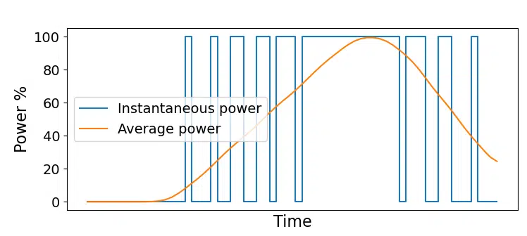
Pulse-width modulation (PWM) is an efficient way to control analog electronics from purely digital FPGA pins. Instead of attempting to regulate the analog voltage, PWM rapidly switches on and off the supply current at full power to the analog device. This method gives us precise control over the moving average of energy provided to the consumer device.
Examples of use cases that are good candidates for PWM are audio modulation (speakers), light intensity control (lamps or LEDs), and induction motors. The latter includes servo motors, computer fans, pumps, brushless DC motors for electric cars, and the list goes on.
See also:
RC servo controller using PWM from an FPGA pin
How PWM works
By switching on and off the power supply to a device with a high frequency, we can accurately control the average current flowing through it. The illustration below shows the basics of how PWM works. The PWM output controls a binary switch that can either set the power to 100% or 0%. By quickly alternating between the two extremes, the sliding window average will be a function of the time spent in each of the states.
Duty cycle
The duty cycle is key to controlling the power given to the analog device in PWM. The term duty cycle means how much time the PWM output spends at the ON position. It’s common to describe the duty cycle as a percentage, as shown in the image below. However, in my VHDL example, I will use an unsigned binary number later in this article. It makes more sense for us to use a binary number, which can represent the full resolution of the duty cycle in our VHDL implementation.
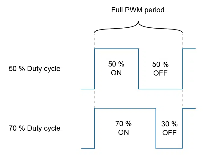
With a duty cycle of 0, the PWM output would remain at the OFF position continuously, while at 100%, it would be non-stop at the ON position. The degree of accuracy that the PWM controller can exert on the payload effect is directly related to the length of the PWM counter. We shall see how this works in the VHDL code when we implement a PWM controller later in this article.
The formula to convert the binary representation of the duty cycle to a percentage is shown below.
\mathit{duty\_cycle\_percentage} = \frac{\mathit{commanded\_duty\_cycle} * 100}{2^\mathit{pwm\_bits} - 1}PWM frequency
When talking about PWM switching frequency, we mean how often the PWM output alternates between the ON and OFF states, how long it takes for the PWM counter to wrap. As always, the frequency is the inverse of the full PWM period:
\mathit{pwm\_freq} = \frac{1}{\mathit{pwm\_period}}The ideal PWM frequency depends on what kind of device you are controlling. Any number larger than a few hundred Hertz will look like a stable light source to the naked eye if the consumer is an LED. For a brushless DC motor, the sweet spot lies in the tens of kilohertz range. Set the frequency too low, and you may experience physical vibrations. With a too fast oscillation, you are wasting power.
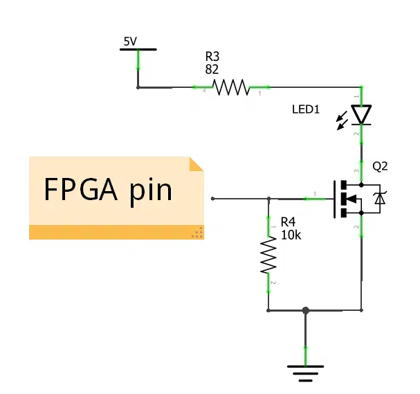
An issue to keep in mind is that the analog power electronics isn’t as fast as the digital FPGA pin. A typical PWM setup uses power MOSFETs as switches to control the current flowing through the analog device.
Consider the schematic shown in the image. It’s part of the LED driver circuit used in my advanced Dot Matrix VHDL course. The FPGA pin controls the gate of the MOSFET, acting as a circuit breaker to the in-series LED. With a higher switching frequency, the transistor will spend more time not being entirely open nor fully closed. That translates into wasted power and excess heat production in the MOSFET.
PWM generator module
Let’s create a standard, generic implementation of a PWM controller in VHDL. What I mean by standard is that this is close to what most experienced VHDL designers would create if you asked them to write a PWM controller in VHDL. It’s generic in the sense that the PWM frequency is customizable to fit most applications.
To test our PWM generator on a real FPGA, we’re going to need a few more modules in addition to the PWM controller. I will present those later when using the PWM module to control the illumination of an LED on the Lattice iCEstick FPGA development board. But first, let’s talk about the PWM generator module.
PWM module entity
To make the module customizable, I have added a generic port that lets you specify two constants at instantiation time.
The first one, named pwm_bits, determines the length of the internal PWM counter. This constant sets the bit length, not the max counter value. You won’t be able to specify the PWM frequency as a specific number of clock periods. But usually, we don’t need to set the PWM frequency with 100% accuracy. The ideal PWM frequency is a range that works well rather than one exact number.
The other generic constant is named clk_cnt_len. It specifies the length of a second counter that effectively lowers the PWM frequency. It acts as a clock divider, but without actually creating a derived clock signal. Note that there is a default value of 1 assigned to it. Setting this constant to 1 disables the clock divider, and it also gets rid of the extra logic that handles it.
I will explain this and present the formula for calculating the exact PWM frequency later in the article.
entity pwm is
  generic (
    pwm_bits : integer;
    clk_cnt_len : positive := 1
  );
  port (
    clk : in std_logic;
    rst : in std_logic;
    duty_cycle : in unsigned(pwm_bits - 1 downto 0);
    pwm_out : out std_logic
  );
end pwm;
Because this is a fully synchronous module, the first two signals are the clock and reset.
The third input on the port declaration list is the duty cycle. As you can see from the VHDL code above, the length of the duty_cycle signal follows the pwm_bits generic constant. This means that the pwm_bits constant governs how precisely you can regulate the power to the analog device.
The final signal on the entity is pwm_out. That’s the PWM modulated control signal, the one that you route to an FPGA pin and connect to the gate of your MOSFET.
PWM module internal signals
The PWM module contains only two internal signals. The first is the PWM counter, which is identical to the duty_cycle input. Just like the latter, the pwm_bits constant also determines the length of this signal.
signal pwm_cnt : unsigned(pwm_bits - 1 downto 0);
signal clk_cnt : integer range 0 to clk_cnt_len - 1;
The second internal signal is named clk_cnt, and as the name implies, it’s for counting clock cycles. It’s of integer type, and if you set clk_cnt_len to 1, the counting range will evaluate to (0 to 0)—just the number 0.
PWM clock cycle counter process
The process that implements the clock counter is straightforward. If the module isn’t in reset, the logic will count clock cycles continuously, wrapping back to zero at the max value that the clk_cnt integer can hold.
CLK_CNT_PROC : process(clk)
begin
  if rising_edge(clk) then
    if rst = '1' then
      clk_cnt <= 0;

    else
      if clk_cnt < clk_cnt_len - 1 then
        clk_cnt <= clk_cnt + 1;
      else
        clk_cnt <= 0;
      end if;

    end if;
  end if;
end process;
Note that if you used the default value of 1 for the clk_cnt_len generic, this process should evaporate during synthesis. The internal if-statement will always be false because 0 < 1 - 1 is false. The value of clk_cnt is then always 0. Most synthesis tools will recognize this and optimize away the entire process.
PWM output process
The process that sets the PWM output signal also controls the PWM counter. It increments the PWM counter when the clock cycle counter is 0. That’s how the PWM frequency limiting mechanism works.
Initially, I intended to write only if clk_cnt = 0 then on line 9, but I discovered that the synthesis tool didn’t remove all the logic related to the clock counter when I used the default clk_cnt_len value of 1. However, including clk_cnt_len in the if-statement did the trick. It shouldn’t have adverse effects on synthesis because clk_cnt_len is a constant. The synthesis tool can figure out its value at compile-time, and then decide if the content of the process is redundant or not.
PWM_PROC : process(clk)
begin
  if rising_edge(clk) then
    if rst = '1' then
      pwm_cnt <= (others => '0');
      pwm_out <= '0';

    else
      if clk_cnt_len = 1 or clk_cnt = 0 then

        pwm_cnt <= pwm_cnt + 1;
        pwm_out <= '0';

        if pwm_cnt = unsigned(to_signed(-2, pwm_cnt'length)) then
          pwm_cnt <= (others => '0');
        end if;

        if pwm_cnt < duty_cycle then
          pwm_out <= '1';
        end if;

      end if;
    end if;
  end if;
end process;
When clk_cnt_len is larger than 1, the pwm_cnt signal behaves like a free-running counter, incrementing when clk_cnt is 0. It’s an unsigned type, which would wrap back to 0 automatically when it overflows. But we have to make sure that it skips the highest value before wrapping to zero.
On line 14 in the code above, I’m checking if the counter is at its second-highest value. If it is, we set it to 0 at this point. I’m using a trick that will work, no matter how long the pwm_cnt signal is. By using the to_signed function, I’m creating a new signed constant with the same length as pwm_cnt, but with the value -2.
The signed number -2 in VHDL, and computers in general, will always be a series of 1’s, and a 0 at the rightmost position. That’s because of how sign extension works. Read more about that in my earlier tutorial:
How to use signed and unsigned in VHDL
Finally, by casting the signed type to an unsigned, we get the second-highest value that pwm_cnt can hold.
On line 18, we are checking if the free-running PWM counter is larger than the duty cycle input. If that is true, we set the PWM output to ‘1’ because we are in the ON period of the duty cycle.
That’s why we had to wrap the PWM counter back to 0 at its second-highest value. If the PWM counter could reach the highest possible value that the duty cycle can have, it wouldn’t be possible to set the duty cycle to 100%. The pwm_cnt < duty_cycle line would always be false when pwm_cnt was at its max value.
It makes sense because we have to represent the fully OFF and ON states in addition to the intermediate duty cycle steps. Imagine that pwm_bits is the set to 2, and run through the entire counting sequence as a mental exercise to see what I mean!
\mathit{pwm\_hz} = \frac{\mathit{clk\_hz}}{\mathit{clk\_cnt\_len} * (2^\mathit{pwm\_bits} - 1)}By taking into account these facts, we can derive the formula shown above for calculating the precise PWM frequency. While clk_hz is the frequency of the FPGA system clock, the other two variables are the generic input constants.
Top module
To test the PWM module on real hardware, I created an implementation that will regulate the illumination of the power-on LED on the Lattice iCEstick. I’m using this affordable FPGA development board in both my VHDL Fast-Track beginner’s course and for my advanced Dot Matrix FPGA course.
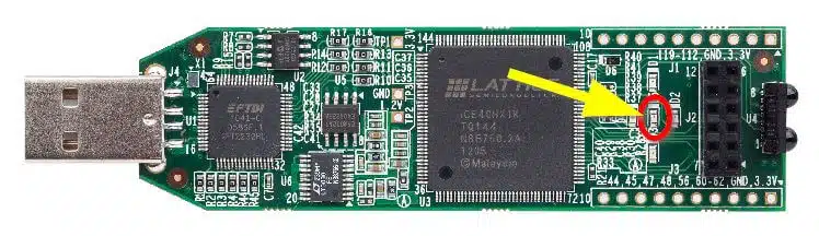
The image above shows the front of the USB-pluggable iCEstick with the power-on LED indicated by the arrow. There are five LEDs on the iCEstick arranged in a star pattern. The power-on LED is green, while the others emit red color light. On the iCEstick, there’s a dedicated FPGA pin for each of the LEDs. Refer to the iCEstick user manual to see the exact pin numbers for controlling them.
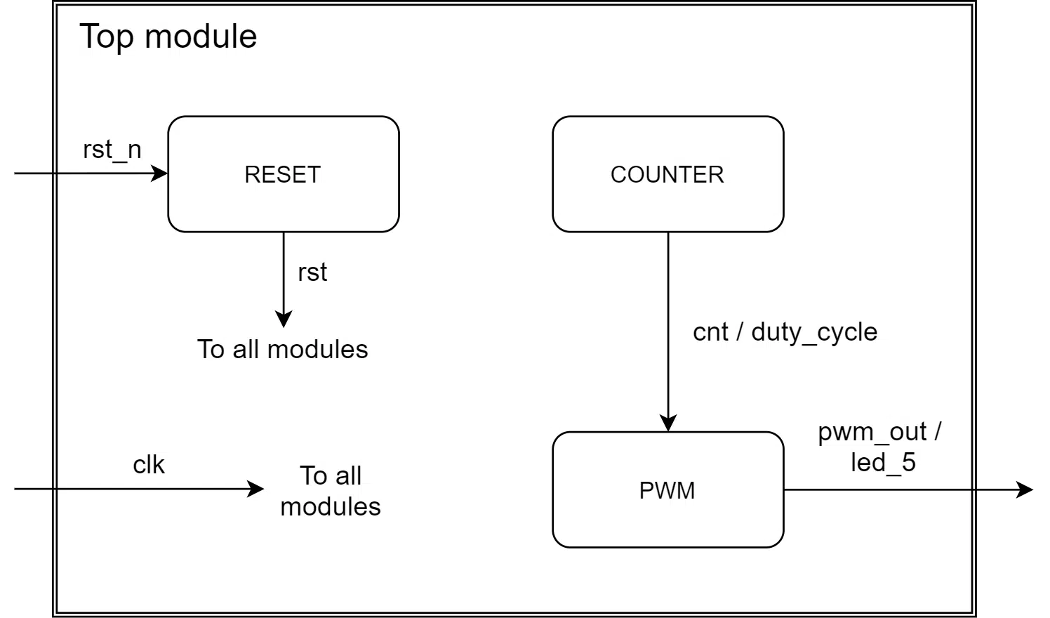
The diagram below shows how the submodules in the top module are connected. We’ve already talked about the PWM module, and I will briefly describe the counter and reset modules later in this article.
Top module entity
Instead of hardcoding the constants inside the top module, I’m declaring them as generics on the top-level entity. Then, I assign default values that are suitable for the iCEstick. One advantage of this approach is that you can override these values in the testbench to speed up the simulation. I don’t assign anything to the generics when I synthesize the design. Thus, the correct default values will end up in the routed design.
We will pass on pwm_bits and clk_cnt_len to the generics on the PWM module entity with the same names. The clock frequency of the iCEstick oscillator is 12 Mhz. By using the formula presented earlier, we can plug in these values to calculate the PWM frequency: \frac{12e6}{47 * (2^8 - 1)} \approx 1 \mathit{kHz}
entity pwm_led is
  generic (
    pwm_bits : integer := 8;
    cnt_bits : integer := 25;
    clk_cnt_len : positive := 47
  );
  port (
    clk : in std_logic;
    rst_n : in std_logic; -- Pullup

    led_1 : out std_logic;
    led_2 : out std_logic;
    led_3 : out std_logic;
    led_4 : out std_logic;
    led_5 : out std_logic
  );
end pwm_led;
You may have noticed that there’s a third constant, cnt_bits, in the generics declaration in the code above. It controls the length of a self-wrapping sawtooth counter. We’re going to use this additional counter to create a gradual illumination of the power-on LED so that we can observe the PWM module working in real-time.
We will connect the high bits of this new counter to the PWM module’s duty cycle input. Because this counter will count clock cycles, the cnt_bits generic determines the pulsing frequency of the power-on LED. The formula, which is a function of the clock frequency and the counter length, is shown below.
\frac{2^{\mathit{cnt\_bits}}}{\mathit{clk\_hz}} = \frac{2^{25}}{12e6} \approx 2.8 \mathit{Hz}In the port declaration, I’ve postfixed the reset input with _n, indicating that the external reset has negative polarity. We will configure the Lattice FPGA to use an internal pull-up resistor on this pin.
Finally, you can see that I’ve listed all the LEDs present on the iCEstick in the port declaration. We’re only going to use LED number 5, but we have to drive the other LEDs actively. If they are left unconnected, they will illuminate in a faint red color.
If you want to take a closer look at the VHDL code and constraints files, enter your email in the form below. You will receive a Zip file with the complete code with ModelSim and Lattice iCEcube2 projects.
Need the Questa/ModelSim project files?
Let me send you a Zip with everything you need to get started in 30 seconds
Tested on Windows and Linux Loading Gif.. 
Top module internal signals
I like to keep my top modules free of RTL logic. It’s a concept that’s called a structural module. In my experience, it’s easier to maintain a structured VHDL project when you separate RTL logic and interconnect. The code below shows the signal declarations in the top module and the concurrent signal assignments.
architecture str of pwm_led is

  signal rst : std_logic;
  signal cnt : unsigned(cnt_bits - 1 downto 0);
  signal pwm_out : std_logic;

  alias duty_cycle is cnt(cnt'high downto cnt'length - pwm_bits);

begin

  led_1 <= '0';
  led_2 <= '0';
  led_3 <= '0';
  led_4 <= '0';

  led_5 <= pwm_out;
First, we declare a reset signal that will be our non-inverted, synchronous version of the external reset.
The second declared signal, named cnt, is the infinitely wrapping clock cycle counter. It’s an unsigned type that will hold the state of our LED intensity sawtooth wave at any given time.
Next is the pwm_out signal. We could have connected the pwm_out signal from the PWM module directly to the led_5 output, but I wanted to observe pwm_out in the simulator. The synthesis tool will figure out that the two signals belong to the same net. It won’t cost additional resources.
Finally comes the declaration of the duty_cycle vector—this time, I used the alias keyword instead of creating a new signal. VHDL aliases work sort of like macros in C. When we use the duty_cycle name from now on, the compiler will substitute it for the high bits of the cnt vector.
After the begin keyword, we assign the pwm_out signal to the led_5 output. All the other LEDs are hard-wired to ‘0’ to prevent them from illuminating red color light.
Instantiations
Before using external signals inside of the FPGA, we must always synchronize them to the internal system clock. Otherwise, we may experience metastability issues, problems that are difficult to debug.
RESET : entity work.reset(rtl)
  port map (
    clk => clk,
    rst_n => rst_n,
    rst => rst
  );
The external reset is no exception, but because I’m not allowing any RTL logic in the top-level structural module, we implement the reset synchronizer as a stand-alone module.
The next instantiation is the PWM module, as shown in the code snippet below. In the PWM module instantiation, we are using the duty_cycle alias for assigning the most significant bits of the cnt vector to the duty_cycle input. That will make the brightness of the LED intensify until the counter reaches its max value. When cnt wraps back to zero, the LED turns off briefly, and the cycle repeats itself.
PWM : entity work.pwm(rtl)
  generic map (
    pwm_bits => pwm_bits,
    clk_cnt_len => clk_cnt_len
  )
  port map (
    clk => clk,
    rst => rst,
    duty_cycle => duty_cycle,
    pwm_out => pwm_out
  );
The third and last instantiation in the top module is the clock cycle counter, as shown below. To make this module more generic, I’ve included a count_enable signal. But in this design, we will set it to a constant ‘1’ because we want to count every clock cycle.
COUNTER : entity work.counter(rtl)
  generic map (
    counter_bits => cnt'length
  )
  port map (
    clk => clk,
    rst => rst,
    count_enable => '1',
    counter => cnt
  );
Leave your email address in the form below if you need the complete VHDL code for this project.
Need the Questa/ModelSim project files?
Let me send you a Zip with everything you need to get started in 30 seconds
Tested on Windows and Linux Loading Gif..
Simulating the PWM LED pulsing
A significant advantage of making the counter lengths customizable through generics is that it allows you to speed up the simulation. Most of the time, we are interested in testing the transitions and events in our logic. We are not that keen on running through an ultra-long counter while nothing else happens in the design.
With generics, we can change these things in a non-invasive way from the testbench. The code below shows the values I assigned to the generic map when instantiating the PWM module in the testbench.
DUT : entity work.pwm_led(str)
  generic map (
    pwm_bits => 8,
    cnt_bits => 16,
    clk_cnt_len => 1
  )
When we simulate using these constants in ModelSim, it’s enough to run for 1400 microseconds at 100 MHz to reveal two full PWM cycles. If we had used the real values, we would have to simulate close to 6 seconds. That’s 32 million clock cycles of almost nothing but counting. It would take forever in ModelSim.
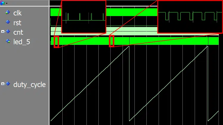
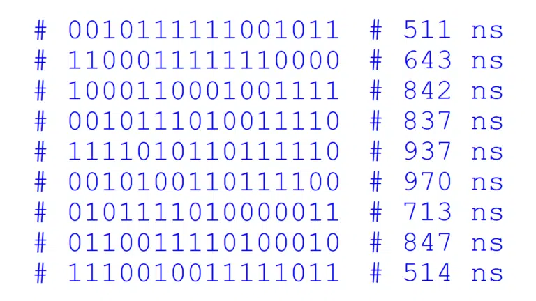
The image below shows the waveform of the PWM simulation in ModelSim. I have changed the format of the duty_cycle signal from the default number type to an analog wave presentation. You can do this in ModelSim by right-clicking on the signal in the waveform and selecting Format->Analog (custom)…, and set the pixel height and data range to match your signal’s min and max values.
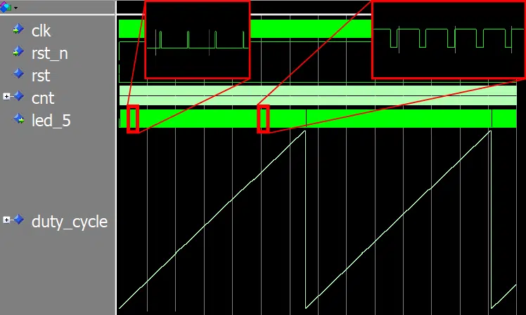
In the waveform, we can see why it’s called a sawtooth signal. The free-running, wrapping counter resembles the teeth on a saw blade.
Notice how the duration of the high periods of the PWM output (led_5) increases as the duty cycle grows. We can also see that led_5 is a continuous ‘1’ very briefly at the tip of the sawtooth. That’s when the duty cycle is 255, the max value.
If we didn’t add the extra if-statement in the PWM module, the one that wraps the pwm_cnt signal back to zero at its second-highest value, we wouldn’t see this. We would never be able to reach the maximum power output. It’s a common error when implementing PWM generators. I’ve done it too once or twice.
The FPGA implementation
I implemented the design on the Lattice iCEstick using iCEcube2, the design software from Lattice. The listing below shows the resource usage reported after place and route. Even though the iCE40 FPGA is tiny, the PWM and supporting modules only use 5% of the available LUTs.
Resource Usage Report for pwm_led

Mapping to part: ice40hx1ktq144
Cell usage:
GND             3 uses
SB_CARRY        31 uses
SB_DFF          5 uses
SB_DFFSR        39 uses
SB_GB           1 use
VCC             3 uses
SB_LUT4         64 uses

I/O ports: 7
I/O primitives: 7
SB_GB_IO       1 use
SB_IO          6 uses

I/O Register bits:                  0
Register bits not including I/Os:   44 (3%)
Total load per clock:
   pwm_led|clk: 1

@S |Mapping Summary:
Total  LUTs: 64 (5%)
After generating the programming bitstream in iCEcube2, I used the Lattice Diamond standalone programmer to configure the FPGA over USB.
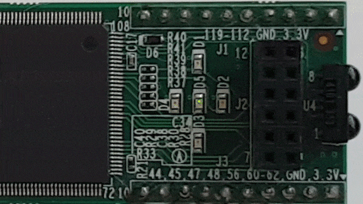
The Gif animation below shows how the sawtooth wave duty cycle signal makes the power-on LED on the iCEstick behave. It illuminates with increasing intensity until the cnt counter wraps. Then, the duty cycle becomes all zeros, and the LED briefly turns off. After that, the cycle repeats indefinitely.
The iCEstick is an inexpensive and versatile FPGA development board. It’s good for beginners, but it’s also suitable for advanced embedded projects. Furthermore, the Lattice software is uncomplicated and easy to use. That’s why I’m using the iCEstick in both my beginner’s VHDL course and in the advanced FPGA course.
If you already own an iCEstick, you can use the form below to download the iCEcube2 project.
Need the Questa/ModelSim project files?
Let me send you a Zip with everything you need to get started in 30 seconds
Tested on Windows and Linux Loading Gif..
Sine wave duty cycle for LED breathing effect
Now you know how to control the illumination of an LED using PWM.
The LED pulsating in a sawtooth wave pattern is arguably cooler than a simple ON/OFF blinking application. That’s a typical first task for VHDL students, and I’m sure that you have flashed an LED at some point in time.
However, LED blinking becomes even more impressive if you use a sine wave to control the duty cycle. The Gif animation below shows our PWM module pulsing the LED with a sinusoid intensity variation over time.
I’m sure you have seen this kind of “breathing” effect on LEDs before. That’s how the notification LED on my mobile phone behaves, and I think it looks natural because there are no abrupt changes in light intensity.
In my next blog post, I will show you how to create a sine wave generator by using block RAM in FPGAs. And we will modify the pwm_led module to pulsate the LED on the iCEstick with sine wave intensity.
Click here to get to the next blog post:
How to create a breathing LED effect using a sine wave stored in block RAM


Nice writeup.
At first I thought this was a super simple topic and there wasn’t much to learn.
It took me more time than i would like to admit to understand the clever trick to achieve true 0% and 100% duty cycle. I think some microcontrollers simply produce small spikes at one of these settings.
You also showed how to “divide” a clock properly without creating a derived clock. I think you might expand this paragraph a bit. Maybe depict this aspect more generally by introducing a clk_enable signal instead of comparing with a magic count value?
Hello, and thanks for commenting!
As always, when you start digging into seemingly simple subjects, it turns out that there are some caveats attached to it.
Yes, the clk_cnt_len counter is my invention. It’s an attempt to make a generic PWM module that you can use for many different applications. But it’s hard to create a module that’s 100% generic without becoming overcomplicated.
Someone already commented in my Facebook group that they needed a PWM module for IR LED transmission. Then you would need to adjust the PWM frequency more accurately than my clock divider allows. Perhaps it would be better to create a clock_enable input to the PWM module and let the user handle the frequency calculation externally.
Hi Jonas,
Good tutorial, thanks for sharing!
Got one question, where the external rst input signal comes from after programming? in the pcf file it’s mapped to pin 90 (pull-up) and looking to the icestick manual that pin goes to the PMOD connector, I guess is an optional external input for reset?
Thanks!
Hello Jose,
That’s some great detective work! ?
You are right. I use the FPGA pin configured with an internal pull-up as an optional reset input.
The RESET module uses a shift register to create a positive internal reset. It releases the internal reset when the shift register fills with ‘1’ after the reset pin is pulled high for several clock cycles.
All registers in the Lattice iCE40 FPGA are initially ‘0’, including the shift register. Therefore, we know that the internal reset will always be active on power-on.
I like this method because it guarantees reset on power-on, and we can choose to connect a button without modifying the VHDL code.
Thank you for the tutorial. In this work you have generated a generic pwm which is useful for a restricted applications. Because the well known pwm is generated by comparison of a reference waveform (constant or sinusoidal) with a triangle waveform. In this case you can control the frequency and the amplitude of the output voltages. Very applicable in variable speed drives. Could you provide us a tutorial on that?
Hello Scofild,
Thanks for the comment. I will put your suggestion on my list of future blog posts. But It will take a while before I get to that, so if you need it now, you will have to search the internet.
Thank you for the tutorial. In this simulation case you set the SET END TIME, GRID SIZE and other settings . Could you provide us the details exactly on that so that i could get the same results on it?
Hello Muhammad,
I assume by GRID SIZE, you mean X and Y resolution of the sawtooth pattern. You can set both by using the ‘pwm_bits’ generic on the top-level entity. The default values are defined in the pwm_led.vhd file, but I override them in the testbench (pwm_led_tb.vhd) to speed up the simulation.
You can download the VHDL files and ModelSim project by using the “Need the ModelSim project files?” form on this page. Open the “How to run.txt” file, and follow the description to replicate my simulation.
I still waiting for the email sir
Hello Muhammad,
I checked the log in my system, and it has been sent to your email address. Perhaps it’s in your spam folder. Unfortunately, it sometimes happens.
If you are using Gmail, you can search for the email by entering in the Gmail search:
in:anywhere from:(jonas@vhdlwhiz.com)
Please mark my email as not spam if you find it in the spam folder.
Thanks.
Hi,
Thank you for this tutorial.
Can you explain while calculating pwm-hz why did you divide clk-hz with (2^pwm-bits-1) ?
I do realize that 2^pwm-bits-1 would give the maximum possible number that can be represented with pwm-bits. But I am not sure if it’s related to this.
Hello,
To make it clear to others reading this comment, this is the formula you are asking about:
pwm_hz = clk_hz/(clk_cnt_len * (2**pwm_bits – 1))
While clk_hz is given by your system clock, pwm_bits and clk_cnt_len are generic constants. You determine them when instantiating the module.
The clk_cnt_len constant is there to allow the user to lower the PWM frequency independently of pwm_cnt. But if we use the default value of “clk_cnt_len : positive := 1”, we can disregard the clock dividing logic.
Then the formula becomes:
pwm_hz = clk_hz / (2^pwm_bits – 1)
The PWM frequency is equal to how many times the internal PWM counter (pwm_cnt) wraps each second. With clk_cnt_len out of the way, it’s a free-running counter that counts at clk_hz speed.
To find out how many times the internal PWM counter wraps each second, we can divide clk_hz by the max counter value (2^pwm_bits – 1).
I hope that helps. Try to do some calculations to convince yourself that it’s correct. For example, if we set clk_cnt_len and pwm_bits to 1, the calculation of the original formula becomes:
pwm_hz = clk_hz / ((2^1 – 1) * 1)
pwm_hz = clk_hz / (1 * (2**1 – 1))
which is equal to
pwm_hz = clk_hz
It checks out correctly.
Hi, I am a student and I am learning VHDL so that can you help me about PWM signal,
I want to RGB led with PWM signal and such as my range 100 to 0 when enter 100 into VHDL simulation RGB led shining red when I decrease the my value RGB led color change.
if you have a time please help me
Hello Hakan,
You can use the PWM module from this article in your project, but you need to create three instances in your top-level architecture, one for each RGB color.
Must it be from 0 to 100? It’s better to use a scale that’s a multiple of two’s because that fits perfectly into a binary number. For example, if you set
pwm_bits => 7the scale is 0 to 127.Download the example project using the Need the ModelSim project files? form in this article and use the testbench as a basis for your project!
thank you for your answer,
my range 0 to 30 celsius so when I typed a value in this range into VHDL simulation page then I want to get 8 bits output to change the colour of RGB led.
Hello,
how can I modify your code to just have a duty cycle as input and not the breathing effect done with cnt_bits ?
Thank you
You can download the example by using the Need the ModelSim project files? form on this page. Then you can grab the pwm.vhd file and throw away the others. Its entity has the duty_cycle input and a pwm_out signal that you can connect to an LED or some other analog device.
Hi Jonas,
Good tutorial, thanks for sharing!
Your article was very helpful. Currently, I am trying to improve the problem by applying an FIR filter to control the exact PWM I want. The problem is that the input has X velocity, through the FIR filter to give the correct PWM. Can you help me do it?
If you want more precise control of the PWM frequency, you can use an integer counter instead of the unsigned type for generating the duty cycle. Check out PWM_PROC in this blog post:
RC servo controller using PWM from an FPGA pin
But you will have to alter the code to get a 50% duty cycle. RC servos only care about the positive half, while I imagine you want both half periods to be of equal length.
Thank you for the tutorial. I would like to know how the entities counter and reset were implemented
Hello, the counter and reset VHDL files are in the project Zip. You can download it by using the “Need the ModelSim project files?” form on this page. I hope you already did that. 🙂
Hello Jonas. How can I slow down the sawtooth counter or, what’s the same, the turning on of the led? I have a board with a 100MHz clock, so I just though that I’ve had to adapt the pwm_hz = clk_hz/(clk_cnt_len * (2**pwm_bits – 1)) equation to my system.
Keeping your same values and adapting to my clock (pwm_bits=8, pwm_hz = 1kHz and clk_hz=100MHz) results that clk_cnt_len=392. I change that in the top module and leave the clk_cnt_len on the “pwm.vhd” empty (not :=1) but the led behaves in the same way, nothing changes. What should I do?
Thanks for your amazing job