The basic logic gates NOT, AND, NAND, OR, NOR, XOR, and XNOR are fundamental building blocks in digital circuits corresponding to Boolean operators.
We refer to them as combinational logic in digital design because their outputs are determined entirely by the combination of input values. One set of inputs always produces a given output. Therefore, we can construct truth tables that list all possible input combinations and their corresponding outputs.
The sections below show interactive ANSI/IEEE symbols, truth tables, Boolean symbols, and VHDL operators for all standard logic gates. I’m using the binary values 1 and 0 in the examples, but you can just as well use the terms true or false.
Play with the switches to see how the outputs change! 😀
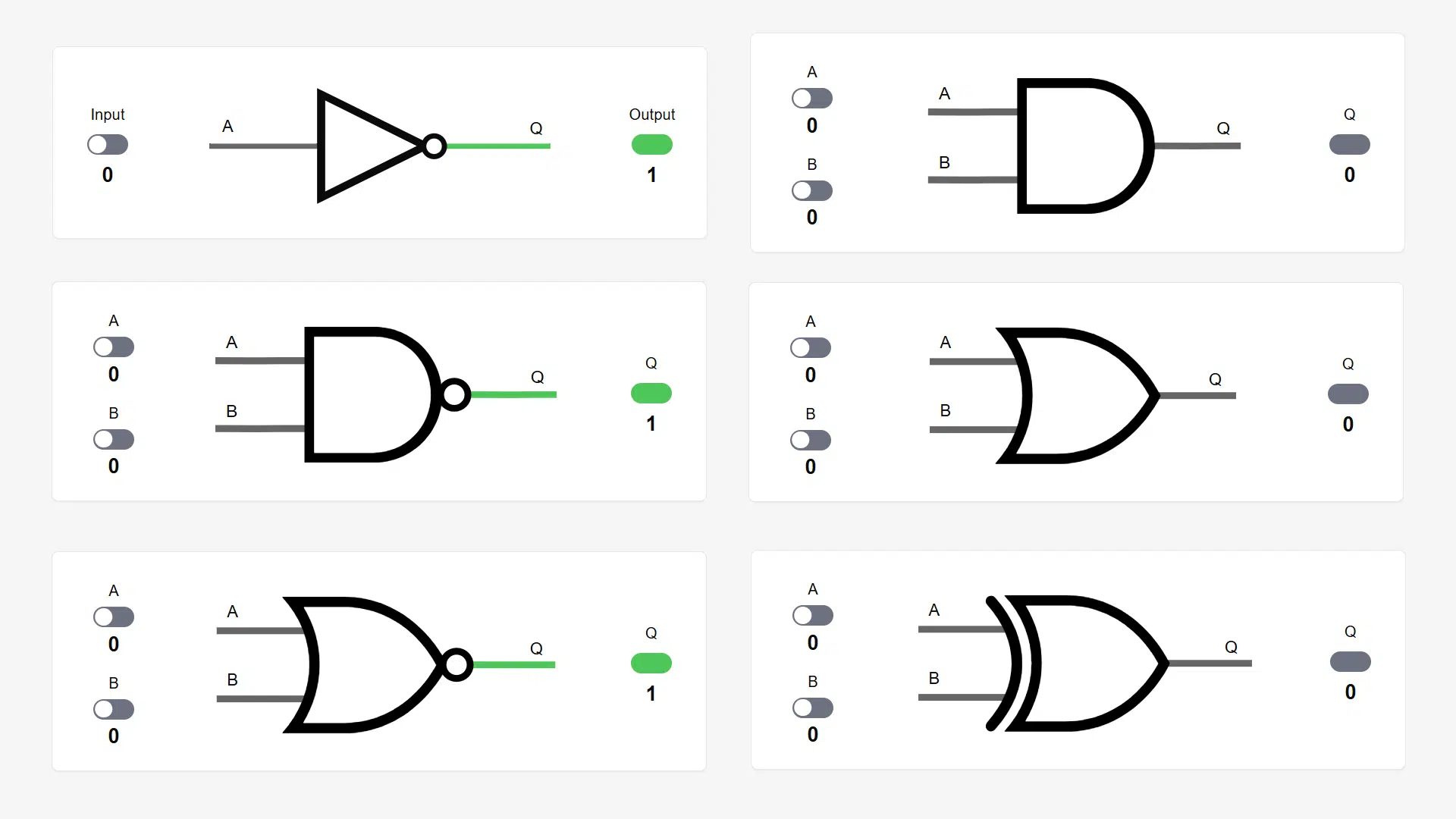
Inverter (NOT)
The inverter, also called a NOT gate, outputs the opposite of its binary input (0 or 1).
The tiny circle or bubble on the output side of the triangle is a symbol for logical inversion. Whenever you see this on any logic gate, it means that the output is the inverse of whatever it would be if the circle weren’t there.
A triangle without the circle is a symbol of a buffer, a circuit that strengthens the output signal without changing it. Thus, the inverter is just a buffer that also inverts the output.
The Boolean expression for the inverter is Q = \overline{A}, and in VHDL, you can use the not operator to invert a '0' value to '1' and vice versa (or false to true).
VHDL code to infer an inverter:
q <= not a;
Note that if a and q are vectors (signals with several wires), the not operator will use several NOT gates to invert every element in the array.
AND gate
The AND gate only outputs 1 if all inputs are also 1. Otherwise, the output is always 0. AND gates may have two or more inputs, but always only one output bit.
The most common notation for the Boolean AND operator is a centered dot: Q = A \cdot B. Often, the dot is omitted: ! = AB, in which case it also means AND logic.
The VHDL and operator performs a logical AND between two values:
q <= a and b;
If the two input operands (a and b) are vectors, they must be of equal length. The product (q) will then also be a vector of the same length, where each element’s value is the ANDing of the corresponding elements in the operands: [q(0) <= a(0) and b(0), …].
In ≥ VHDL-2008, you can also use the unary and operator:
q <= and slv;
Given that the right-hand operator is a vector of binary or Boolean values like signal slv : std_logic_vector(7 downto 0), it will produce the logical AND of all the elements in that array.
NAND gate
The NAND gate is simply an AND with the output inverted. Each value in the truth table is the opposite of that in the AND’s truth table.
NAND gates are particularly interesting in digital logic design because you can construct all other logic gates from them (NAND logic). If you only had access to NAND gates, you could build a complete, functioning digital design by arranging and interconnecting them cleverly.
The Boolean operator for the NAND is the same as for the AND, but with a line above the whole expression to indicate its inverted output: Q = \overline{A \cdot B}, or just Q = \overline{AB}.
The VHDL operator is nand:
q <= a nand b;
This operator also works on single values as well as vectors, and there’s a unary nand operator (≥ VHDL-2008) that NANDs together all the array elements if used on a single right-hand operand:
q <= nand slv;
OR gate
The OR gate outputs 1 if any of the N inputs are 1. Thus, it only outputs ‘0’ when all inputs are 0.
A NAND gate is functionally equivalent to an OR gate with inverters attached to all inputs. That is one of two rules known as De Morgan’s law: \overline{A \cdot B} = \overline{A} + \overline{B}
The Boolean operator for the OR gate is the plus symbol, written as Q = A + B and the VHDL operator is or:
q <= a or b;
The or operator also supports single values and vectors, and there’s a unary version in ≥ VHDL-2008 that takes only a right-hand array operand and reduces it to a one-bit value:
q <= or slv;
NOR gate
The NOR gate behaves like an OR gate with the output inverted. Its truth table has values that are opposite to the OR’s table.
A NOR gate is functionally equivalent to an AND gate with inverters attached to all inputs, as stated by the second part of De Morgan’s law: \overline{A + B} = \overline{A} \cdot \overline{B}.
Because of that and other properties, NOR gates can be interconnected in ways that allow them to implement all other logic gates (NOR logic). Thus, you can build complete digital designs with only NOR gates.
However, NAND logic technology is more common than NOR-only designs. In CMOS technology, NAND gates are typically faster and require fewer transistors than NOR gates. That doesn’t apply to FPGA designs since the same lookup table (LUT) primitives implement all logic gates.
The Boolean expression for NOR is that of an OR with an inverting line above Q = \overline{A + B}, and the VHDL nor operator works as follows:
q <= a nor b;
It works on single-bit values or vectors, and there’s also a unary nor operator (≥ VHDL-2008) that takes a right-hand array operand only:
q <= nor slv;
XOR gate
The XOR gate outputs 1 if only one of the inputs has the value 1. If none, two, or more inputs are 1, the output will be 0.
While XOR isn’t used much in programming, it’s more common in digital designs due to its usefulness in half adders, parity checking, and cryptography.
XOR (and XNOR) are typically the most expensive gates to implement in CMOS due to the higher number of transistors needed. In FPGA designs, they don’t consume more than other gates because all gates are realized through the use of lookup tables (LUTs).
The Boolean operator for XOR is a plus in a circle: Q = A \oplus B, and the xor VHDL operator works on left and right-hand operands like this:
q <= a xor b;
The two operands may be vectors, in which case, corresponding vector elements will be XORed to create the elements in the output vector.
Perhaps the most useful of the unary operators is the unary xor. You can use it to generate parity bits, among other things:
even_parity_bit <= xor data;
XNOR gate
The XNOR gate is equivalent to an XOR with inverted output. Its output will only be 1 when all inputs are the same (0 or 1).
Among other things, you can use it as a comparator to check that data has expected values. If A matches B, the output is true; otherwise, it is false.
The Boolean operator for XNOR is usually a dot in a circle: Q = A \odot B, and the xnor VHDL operator has a two-operand version:
q <= a xnor b;
The code above works with single-bit values or vectors, while the unary xnor operator is most useful for parity checking:
odd_parity_bit <= xor data;


Hi Jonas, yours last wrote is “odd_parity_bit <= xor data;"
May be – xnor?