This is a guest article by Espen Tallaksen, whom I (Jonas) know from my time working as an FPGA developer in Norway. Espen is the CEO of EmLogic, an embedded system and FPGA design company. Espen has also contributed greatly to the VHDL community by developing and maintaining UVVM, which this article is about. This is not paid content.
By Espen Tallaksen, CEO, EmLogic
According to Wilson Research, around half the development time for an FPGA is spent on verification. I think it is possible to significantly reduce this time, with only minor adjustments and no extra cost.
Even worse, almost half the verification time is spent on debugging. This includes debugging of both the DUT (Design Under Test) and the Testbench itself, but is, in my opinion, a far too large percentage of the total development time.
For an FPGA design, we all know that the architecture, all the way from the top to the micro architecture, is critical for both FPGA quality and the development time. It should be obvious that this also applies to the testbench. The Universal VHDL Verification Methodology (UVVM) was developed to solve this and will reduce the verification time significantly while at the same time improving the FPGA quality.
UVVM is a free and open source VHDL verification library and methodology, and provides the best VHDL testbench approach possible. With its straightforward and powerful architecture, it allows designers to build their own test harness and test cases much faster than ever before. Equally important is efficient reuse at all levels. UVVM has a unique reuse structure, making it a game-changer for efficient FPGA development and testbench reuse.
This has led to a very fast adoption of UVVM in the FPGA community. Currently, more than 27% of all FPGA designers worldwide use UVVM, and the number is much higher when considering VHDL designers only. Interestingly enough, UVVM is also the most popular VHDL verification methodology for ASIC designers.
Since 2017, we have had a tight cooperation with ESA (the European Space Agency) on improving and extending the functionality, and now we have just completed our 3rd ESA UVVM project, providing even more verification and debug functionality.
This article will give you an introduction to UVVM, show you how simple it is to understand and get started, and also show how UVVM will help you make better VHDL testbenches and significantly improve both FPGA quality and verification efficiency.
Enabling efficiency and quality
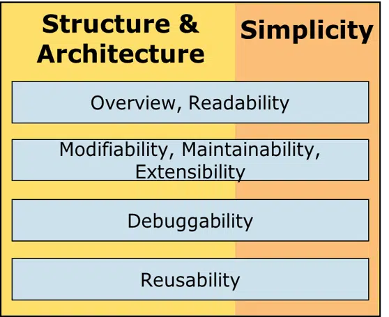
Most designers know that for FPGA design, there is a strong correlation between efficiency & quality and the following design characteristics: Overview, Readability, Modifiability, Maintainability and Extensibility. But these are, of course, equally important for testbenches and verification. Additionally, debuggability is also essential, as this accounts for almost 25% of the FPGA development time. Finally, reusability from one project to another is always important, but for verification, there is also a huge improvement potential between module testbenches (TB) in one single project, and also from the module TBs to the top-level TB.
Improving architecture and simplicity
In order to achieve these improvements, you need a really good testbench architecture, not just at the higher level, but all the way down to testbench micro architecture. Now, to achieve good efficiency and quality, only one critical aspect is missing: Simplicity.
Of course, – for a complex FPGA the verification can seldom be simple, but the key is “as simple as possible” or more precisely “as simple as possible for the tasks where you spend most of your time”, and for verification that would be to make all the different test cases, i.e. writing the various test sequences. The other main aspects of making a testbench are the test harness and any potential verification support procedures, processes and entities. UVVM has targeted all of this.
What UVVM offers
So, what is UVVM?
Well, first of all, it is a Free and Open Source VHDL Verification Library and Methodology providing the following:
- A testbench infrastructure with basic commands for any VHDL testbench
- BFMs (Bus Functional Models) for many common FPGA peripherals/interfaces
- Specification Coverage for Requirements Tracking
- A very structured testbench architecture for more advanced verification challenges
- VHDL Verification Components (VVCs) for many common FPGA peripherals/interfaces
- A very structured VVC architecture that allows BFMs to be controlled simultaneously and in a very controlled manner
- Transaction Level Modelling – for high-level control of the testbench
- Advanced and Optimized Randomization for Constrained Random
- Functional Coverage
- Various other verification support modules like Scoreboards, Error injector, Watchdogs, etc.
UVVM provides VHDL users with a methodology and library allowing a stepwise evolution of their testbenches for simple, via medium – to complex DUTs, so that the user can take the next step in verification complexity only when needed. So, let us start with the entry level, – just to show how easy this is and how much it gives you.
Starting out with UVVM
A good starting point for using UVVM is to evaluate what is always required for any good testbench, independent of DUT complexity:
- Logging – with good messages
- Alert handling – with good messages
- Checking values and time aspects
- Waiting for something to happen
- Randomization (not always, but often)
We can exemplify this by looking at the most important testbench functionality for a very simple module like a basic interrupt controller with N interrupt sources, a resulting interrupt to the CPU and a register interface (SBI = Simple Bus Interface) for software access, as shown in Figure 2.
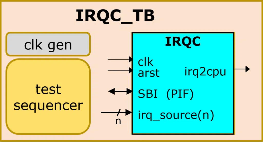
In every testbench, we also need a clock controller, and in UVVM you can choose between several variants, with the simplest version as follows:
clock_generator(clk, C_CLK_PERIOD);
This is just a simple procedure call that you put into your testbench architecture. When putting a procedure call directly in the architecture and not inside a process, this will be a so-called concurrent procedure, which works exactly like a process. Thus, clock_generator() works exactly like a full clock process. There are lots of clock generator variants available in UVVM. You can then write your test sequencer inside your test process as shown below:
log("Check Interrupt trigger and clear mechanism");
check_value(irq2cpu, '0', "irq2cpu default inactive");
check_stable(irq2cpu, now – v_reset_time, "irq2cpu initially stable off");
gen_pulse(irq_source(3), '1', C_CLK_PERIOD, "Set IRQ source for 1T of clk");
await_value(irq2cpu, '1', 0 ns, 2* C_CLK_PERIOD, "Interrupt expected")
All the commands here are self-explanatory, which makes it easy to read and modify. The message provided as the last parameter is what you would normally write as a comment, but including it in the procedure call allows the message to be written to the transcript/log if something fails, or as a positive acknowledge if you want that. The resulting output from the above commands would be as shown below. You can also include a log prefix, message ID and scope in this log output:
2000.0 ns  Check Interrupt trigger clear mechanism
----------------------------------------------------------------------------
 110.0 ns  check_value() => OK, for std_logic '0'. irq2cpu default inactive
 727.5 ns  check_stable() => OK. Stable at 0. irq2cpu initially stable off
1060.0 ns  Pulsed to '1'. Set IRQ source for 1T of clk
1117.5 ns  await_value(std_logic 1, 0 ns, 20 ns) => OK. Interrupt expected
All the commands shown above are available from the UVVM Utility Library, a testbench infrastructure library with lots of very useful functions and procedures. In addition to the ones mentioned above, there are similar, very simple-to-use functions for string handling, randomization, waiting for signal stability, flags and synchronization mechanisms, normalization, verbosity control, etc.
BFM procedures
The next logical step would be to use Bus Functional Model (BFM) procedures for accessing the various DUT-internal software accessible registers. In the example below, we first write something to the Interrupt Trigger Register (ITR) and then read back the Interrupt Request Register (IRR) and check that the value is as expected:
sbi_write(C_ADDR_ITR, x"A0", "ITR: Set more interrupts");
sbi_check(C_ADDR_IRR, x"A5", "IRR: Check updated value");
The result would then be as follows:
2020.0 ns    SBI write(A:x"2", x"A0") completed. ITR: Set more interrupts
2040.0 ns	 SBI check(A:x"0", x"A5") ==> OK, IRR: Check updated value
Then in your test sequencer, you use all these procedures and many others to check various functionality inside your module, and finally, you write out an alert summary. You can then use this summary or the provided status summary shared variable as input to your regression testing tool.
You can watch one of our free webinars for Siemens, Aldec and others for a more thorough introduction.
BFM procedure limitations
BFM procedures are great for accessing interfaces, as you only need to call a procedure. All of the protocol details, signal wiggling, sampling, etc, are then handled for you and you don’t even have to understand the interface or protocol. Also, it allows changes to the protocol and interface without changing the BFM procedures or the calls from the sequencers.
There is, however, one major limitation with BFMs: they are blocking. That means when executing the BFM, nothing else can be done inside the process in which the BFM is executed. Thus, when executing a BFM inside a test sequencer, the test sequencer cannot do anything else until the interface access is finished. So, for instance, a UART test sequencer cannot transmit data into the DUT RX input at the same time as reading a previously received byte via the CPU interface. As this is a very typical error-prone scenario, a testbench should definitely test simultaneous activity on all channels.
Designers who are aware of this typically handle the three independent UART interfaces (RX, TX and CPU interface) from three different test processes. The problem with that approach is that in order to find the very error-prone cycle-related corner cases in such scenarios, you need to carefully control the interactivity on these interfaces.
The normal way to handle this is to apply various synchronization mechanisms between these processes, typically by sending trigger signals or semaphores back and forth. This might seem like a structured approach, but you very soon lose the overview. This means you can forget about readability, maintainability, debuggability and reusability. It is much easier to control everything from one single brain – in this case a single sequencer, provided you have the right testbench architecture. Here, UVVM is a major step forward.
Simple control of multiple interfaces
UVVM’s VVC (VHDL Verification Component) system allows simultaneous activity on multiple interfaces to be controlled in a very structured and simple manner, by distributing, in zero time, the execution of the BFM procedures to VVCs. UVVM even allows for delays to be inserted before or after any BFM execution. This means the test sequencer has full control over the complete verification environment, and you can easily see what will happen in your testbench at any time by just looking at the test sequence in one single process, and not multiple processes.
UVVM also allows VVCs to be controlled from multiple test controllers, but I would certainly not recommend that unless you really need to, – which is very seldom. A nice feature here is that for these special scenarios, UVVM in fact even allows one single VVC to be controlled from multiple sequencers.
Switching from BFM to VVC
Seen from the test sequencer, the switch from using BFMs directly to using VVCs is quite simple. You just use a slightly different set of procedures, where the most important difference is the added target parameters. These target parameters say which verification component will handle the actual execution of the BFM, so in fact, the VVC command is just a non-time-consuming distribution of a BFM command to the given VVC. And this non-time-consuming distribution means that the test sequencer is not blocked, but can distribute commands to multiple interfaces simultaneously and then even do something by itself in parallel.
Figure 3 shows a BFM-based TB to the right, where the test sequencer has direct access to the interfaces of the DUT, and uses BFMs to access these, one at a time. To the left, a VVC-based TB is shown. Here, the VVCs are connected directly (port-mapped) to the various interfaces of the DUT, and the test sequencer sends non-time-consuming commands to the various VVCs. Note that the VVCs will then immediately start executing the corresponding time-consuming BFM procedures towards the DUT.
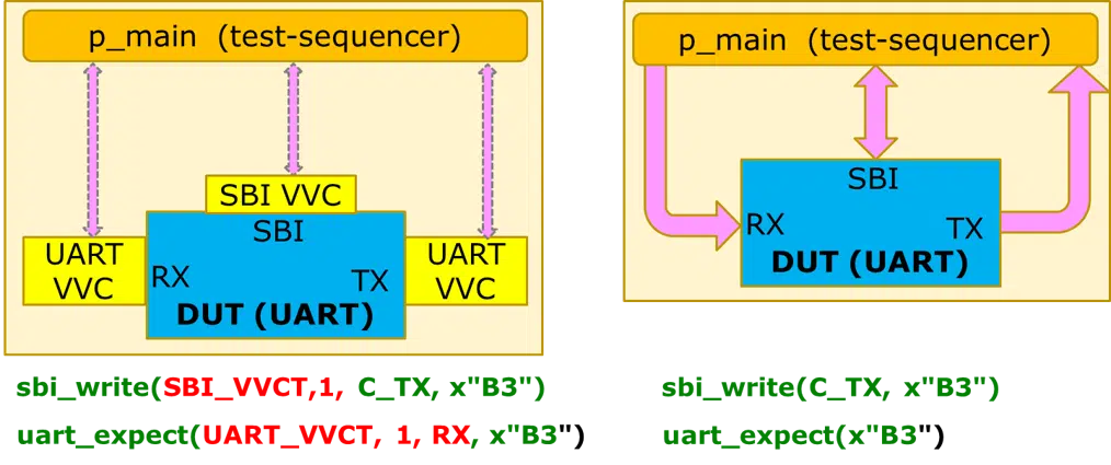
The test sequencer thus has full control of what is happening on the DUT’s interfaces and may use the await_completion() and insert_delay() commands to synchronize to any VVC’s BFM execution. await_completion() will stall the test sequencer until a given VVC has finished executing either all its commands or just a given command. This way, the test sequencer has full overview of the testbench status and knows when to issue commands to the various VVCs. The insert_delay() command allows the test sequencer to offset or skew VVC interface handling with respect to each other, and thus target cycle-related corner cases.
Overview, Readability, Maintainability, Modifiability and Extensibility
If your DUT is quite simple, you can probably manage with BFMs only. The VVCs are intended for medium to high complexity modules and FPGAs (or ASICs), but note that complexity here is seen from a verification point of view. As such, even a simple UART would benefit from using VVCs. This is, of course, also a question of quality. If you can accept a UART byte error every 10,000 bytes, then you can lower your verification level and effort. If not, VVCs will help you a lot in detecting those types of bugs.
For simple testbenches, the use of the UVVM Utility Library and BFMs would be sufficient, and if not, then at least a very good starting point. You might think that the improvement potential is not that big for a simple testbench, but even for a small project you could easily have a saving potential of 50-300 hours (or in the range 10-30% or more on the total project time), and at the same time improve the quality. For more complex modules or FPGAs, the savings potential could be much higher, even percentage-wise.
And by the way, UVVM has by far the largest amount of free Open Source VHDL BFMs and VVCs available (see Figure 4).
Figure 4: Free BFMs and VVCs available in UVVM
AXI stream VVC example
It probably makes sense to also show an AXI stream example in this article, as the AXI stream interface is used in many FPGA projects today. Here we can also show a very interesting additional feature in UVVM.
But, first, – when making a testbench for a DUT with one or more AXI stream interfaces, you can use both the BFM and the VVC approach, – with the pros and cons as given above. For the DUT shown in Figure 5, using the VVC approach will detect more potential problems in the data flow and interfaces in a simpler way than the BFM approach.
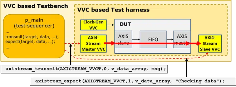
The figure illustrates, in a very simple example, how the test sequencer issues two commands to the test harness; – the axistream_transmit() to the master VVC, and the axistream_expect() to the slave VVC. These two commands are issued at the same time (only delta cycles apart) from the test sequencer to the VVCs. Transmission will then start immediately (at the same time) from the master VVC towards the DUT, whereas the slave VVC will be waiting for data to arrive out of the DUT, and then check the actual data received against the expected. The protocol is then obviously also confirmed.
Data flow control is error-prone
The AXI stream protocol allows feed-forward control and backpressure. This is useful to adapt both to external interfaces and to internal data processing. Experience shows that this mechanism can be quite error-prone in many scenarios.
For that reason, UVVM has introduced both directly and randomly controlled manipulation of the ‘valid’ and ‘ready’ signals in the AXI protocol, for deactivation at any given position and for any number of clock cycles. According to many UVVM users, this feature has enabled lots of bug detection in their design.
More advanced testbenches
Complex DUTs require more advanced testbenches. Such testbenches could include enhanced randomization, functional coverage, specification coverage, error insertion, watchdogs, scoreboards, and more. This might seem overwhelming, but it will, in fact, result in better quality and far more efficient verification.
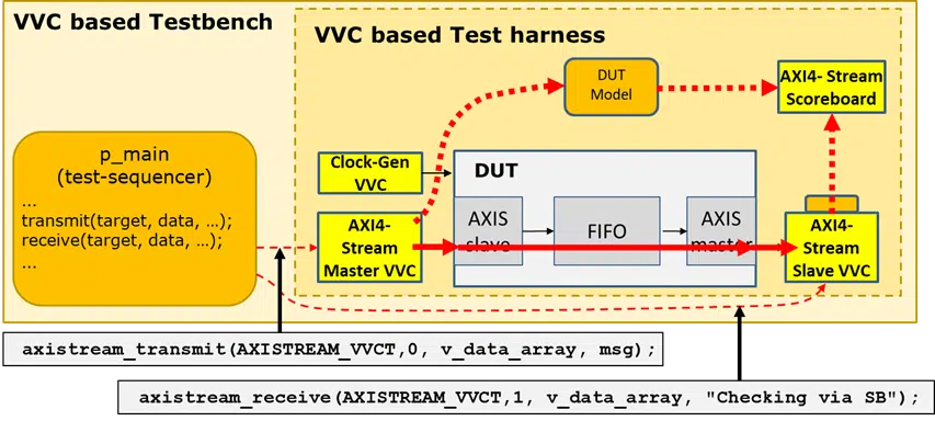
Figure 6 shows again an AXI-stream oriented DUT and testbench using VVCs, but in this figure we have also introduced a Scoreboard, a Model and transfer of transaction info. Here you will hopefully see a pattern with UVVM. All the yellow boxes are well-known functionality with a well-known and standardized interface, and the more these well-known boxes dominate your test harness, the easier it will be to get a good overview and understanding of the complete testbench and how the test sequencers operate.
This yields a huge advantage, as all you have to do and all you have to examine to understand the complete testbench and your test cases, is the orange stuff – the testbench dedicated code. And in UVVM, the test case dedicated test sequencers can be written so that even HW and SW designers can understand them. This reduces the total verification effort to a fraction compared to other verification methodologies.