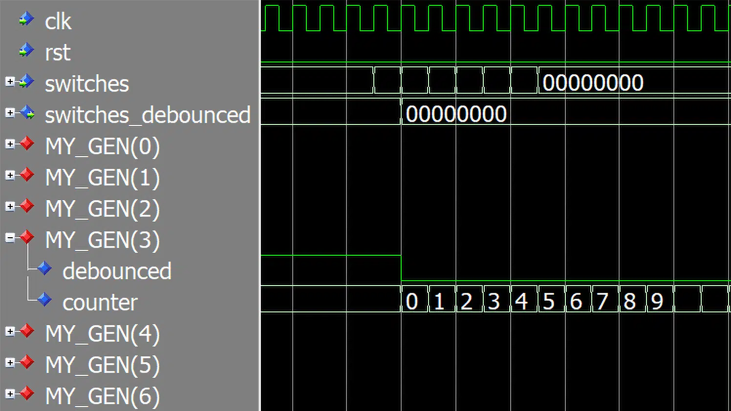
The generate statement in VHDL can automatically duplicate a block of code to closures with identical signals, processes, and instances. It’s a for loop for the architecture region that can create chained processes or module instances.
Unlike a regular for loop, which can only exist in a process or a subprogram, the generate statement is placed directly in the architecture region of the VHDL file. When used together with generics, it becomes a powerful tool for designing customizable VHDL modules that allow for reuse across designs.
Generate statement syntax
The syntax of the generate statement is as follows:
[label :] for <constant_name> in <range> generate
  [declarations_local_to_each_loop_iteration]
[begin]
  <processes_and_instantiations>
end generate [label];
The parts enclosed in square brackets are optional. Thus, you may omit the declarative region and the begin keyword if you don’t want to declare any local objects. The <range> placeholder represents a standard integer range using to or downto.
One-bit switch debouncer
Before we start on the generate statement, I will present a simple module that we will use as an example throughout this article. It’s a debouncer capable of debouncing a single switch input.
To make it usable for any clock speed, I’ve added a generic input named timeout_cycles. This constant specifies how many clock cycles the timeout will be after the switch input changes. The debouncer will ignore any additional change in the switch value during the timeout period.
The listing below shows the entity of the debouncer module. There’s a bouncy switch input, and then there’s the clean switch_debounced output.
entity debouncer is
  generic (
    timeout_cycles : positive
    );
  port (
    clk : in std_logic;
    rst : in std_logic;
    switch : in std_logic;
    switch_debounced : out std_logic
  );
end debouncer;
The debouncer module relies on an integer counter to achieve the timeout period. The length of the counter signal follows the generic constant. That’s what the timeout duration specified during instantiation does.
Because we need to read the value of the switch_debounced output internally, I’ve declared a shadow signal named debounced, which we will use in its place. That’s a cleaner solution than the other option, which is to set inout mode on switch_debounce in the entity.
Finally, we implement the debouncing behavior in a single process, as shown in the code below.
architecture rtl of debouncer is

  signal debounced : std_logic;
  signal counter : integer range 0 to timeout_cycles - 1;

begin

  -- Copy internal signal to output
  switch_debounced <= debounced;

  DEBOUNCE_PROC : process(clk)
  begin
    if rising_edge(clk) then
      if rst = '1' then
        counter <= 0;
        debounced <= switch;

      else

        if counter < timeout_cycles - 1 then
          counter <= counter + 1;
        elsif switch /= debounced then
          counter <= 0;
          debounced <= switch;
        end if;

      end if;
    end if;
  end process;

end architecture;
The waveform below shows a simulation of the debounce module in ModelSim. We can see that the switch_debounced output follows the switch input, but it ignores the immediate bouncing behavior after the first change — it debounces the signal.

Use the form below to download the VHDL code from this article. When you enter your email address, you will receive a Zip file containing the entire ModelSim project with testbenches and a quick-run script. You will receive future updates from VHDLwhiz, and you can unsubscribe at any time.
Generate for loop with instantiations
To make a debouncer for an array of switches, we’re going to use a generate statement to create multiple instances of our one-bit debouncer module.
The listing below shows the entity of our new array or vector debouncer module. It’s similar to the one-bit debouncer, but there’s an additional generic input: switch_count. It specifies how many instances of the debouncer module to create. There should be one for each switch.
Furthermore, I’ve renamed the switch input and output to the plural versions of the word, and they are now vectors instead of single bits.
entity debouncer_gen_inst is
  generic (
    switch_count : positive;
    timeout_cycles : positive
    );
  port (
    clk : in std_logic;
    rst : in std_logic;
    switches : in std_logic_vector(switch_count - 1 downto 0);
    switches_debounced : out std_logic_vector(switch_count - 1 downto 0)
  );
end debouncer_gen_inst;
In the architecture, it’s time to use the generate statement. It works like a regular for loop, only with the word “generate” replacing the word “loop”. But unlike a regular for loop, it can contain module instantiations.
The for loop runs at compile time and generates one instance of the debouncer module for each iteration. But because the “i” constant will be different for each iteration, we can use it to map the inputs and outputs of the debouncers to individual bits on the switches vectors, as shown below.
architecture rtl of debouncer_gen_inst is
begin

  MY_GEN : for i in 0 to switch_count - 1 generate

    DEBOUNCER : entity work.debouncer(rtl)
    generic map (
      timeout_cycles => timeout_cycles
    )
    port map (
      clk => clk,
      rst => rst,
      switch => switches(i),
      switch_debounced => switches_debounced(i)
    );

  end generate;

end architecture;
Note that it’s optional to label the generate statement, but it may be wise to do so. The label appears in the simulator hierarchy and the synthesis log, making it easier to identify the specific instance when debugging.
The waveform below shows a simulation of the vector debouncer. We can see that the “MY_GEN” label reappears here, with indexes added for each of the eight debouncer instances.
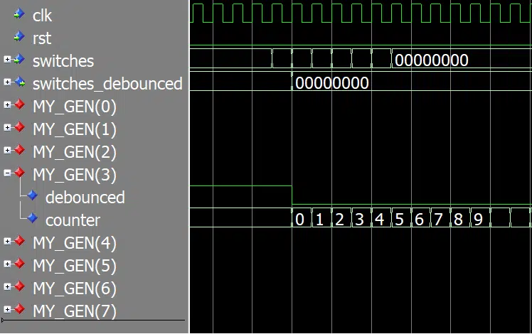
This testbench only changes the switch number 3 input, that’s what you see in the waveform and why I’ve expanded only the MY_GEN(3) group.
You can quickly run this example on your computer if you have ModelSim installed. Use the form below to download the source code and the ModelSim project!
Generate for loop containing processes
In the last example of this article, we will be using a generate statement to make a series of identical processes. Instead of creating instances of the one-bit debouncer module, I’ve lifted the VHDL code from it. The entity is the same as in the previous example, and so is the behavior, but the implementation is different.
We can see that I’ve moved the DEBOUNCE_PROC process within the generate statement and changed it slightly in the code below. This time I’m declaring two local signals within the generate statement: debounced and counter.
Each iteration of the for loop will create an additional copy of the signals and the process. Using these signal names within the process will reference the ones scoped to the enclosure of that specific loop iteration.
Finally, I’m assigning the debounced std_logic signal to the correct bit of the switches_debounced module output using a concurrent statement above the process.
architecture rtl of debouncer_gen_proc is
begin

  MY_GEN : for i in 0 to switch_count - 1 generate

    signal debounced : std_logic;
    signal counter : integer range 0 to timeout_cycles - 1;

  begin

    switches_debounced(i) <= debounced;

    DEBOUNCE_PROC : process(clk)
    begin
      if rising_edge(clk) then
        if rst = '1' then
          counter <= 0;
          debounced <= switches(i);

        else

          if counter < timeout_cycles - 1 then
            counter <= counter + 1;
          elsif switches(i) /= debounced then
            counter <= 0;
            debounced <= switches(i);
          end if;

        end if;
      end if;
    end process;

  end generate;

end architecture;
I’ve omitted the simulation waveform because it looks precisely the same as in the previous example using module instantiation. The behavior is identical.
You can download all the code using the form below. When you enter your email address, you subscribe to updates from VHDLwhiz. But don’t worry, there is an unsubscribe link in every email that I send.
Leave a comment below if you have another useful application for generate statements to share!



Thank you for all your tutorials!
I am in the early stages of learning VHDL at UiO and hope to check if my summary-version of this article is correct, so that I don’t teach anything incorrect to my fellow students when I try to explain this to them.
Summary understanding:
The generate statement is not a concurrent statement similar to any other statement, it’s a piece of code which is ran at compile time and can be seen as a way of generating VHDL-code rather than manually writing the “same” thing over and over again. Say you want to write the following code:
architecture RTL of entity is
    signal din     : std_logic_vector(0 to n);
    signal dout : std_logic_vector(0 to n);
begin
    dout(0) <= din(0);
    dout(1) <= din(1);
    ...
    ...
    dout(n) <= din(n);
end architecture RTL;
Here we’re basically writing the same line over and over again, instead of writing them by hand we should GENERATE them! Like this:
architecture RTL of entity is
    signal din     : std_logic_vector(0 to n);
    signal dout : std_logic_vector(0 to n);
begin
  for i in 0 to n generate
      dout(i) <= din(i);
  end generate;
end architecture RTL;
Since we’re generating lines of code for the compiled version, ANY code which can be written in the architecture can also be written inside of a generate. Witch the natural catch that if you want to connect anything you create inside the generate statement to anything else in your code, you need to do so through signals.
Would I be safe if I tried to use this as my elevator-pitch to my fellow students?
Yes, you’ve got it right. Generate statements are evaluated during elaboration before synthesis or simulation starts, and they make copies of whatever you put inside.
Your trivial example is correct, although the generate statement doesn’t offer any benefit in that particular case since we could just have written
dout <= din;.The most powerful use case of generate statements is when we need to create multiple instances of a module based on the value of a generic constant. And you can combine that with generating processes and intermediate signals too.
Check out this example of a totally imaginary image processing module to get some ideas for how you can use VHDL's generate statement to resize your design based on a generic constant:
entity image_processor is
  generic (
    STAGES : positive := 5
  );
  port (
    clk : in std_logic;
    rst : in std_logic;
    unprocessed_pixel  : in  unsigned(23 downto 0);
    processed_pixel : out unsigned(23 downto 0)
  );
end entity image_processor;

architecture rtl of image_processor is

  type arr_type is array (0 to STAGES - 1) of unsigned(23 downto 0);
  signal pipeline : arr_type;

begin

  pipeline(0) <= unprocessed_pixel;
  processed_pixel <= pipeline(STAGES - 1);

  GEN_PIPELINE : for i in 1 to STAGES - 1 generate

      signal reg_pixel : unsigned(23 downto 0);

    begin

    -- Combinational logic module
    FILTER_INST : entity work.pixel_filter(rtl)
      port map (
        in_pixel  => pipeline(i - 1),
        out_pixel => reg_pixel
      );

    -- Pipeline register
    FF_PROC : process(clk)
    begin
      if rising_edge(clk) then
        if rst = '1' then
          pipeline(i) <= (others => '0');

        else
          pipeline(i) <= reg_pixel;

        end if;
      end if;
    end process;

  end generate;

end architecture rtl;