Similar Posts
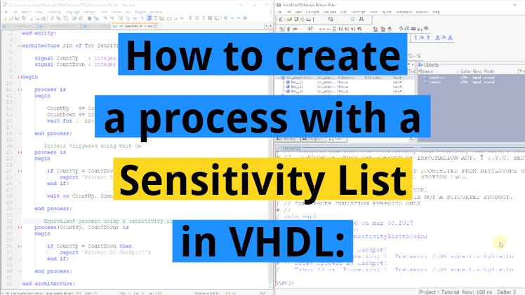
How to create a process with a sensitivity list in VHDL
You should always use a sensitivity list to trigger processes in production modules. Sensitivity lists are parameters to a process which lists all the signals that the process is sensitive to. If any of the signals change, the process will wake up, and the code within it is executed. We’ve already learned to use the…
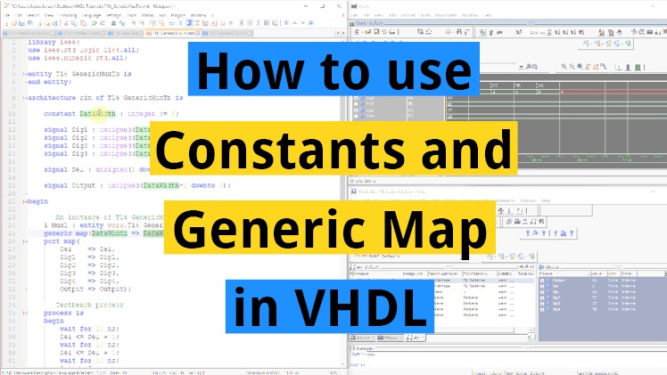
How to use constants and Generic Map in VHDL
Creating modules is a great way to reuse code, but often you need the same module with smaller variations throughout your design. This is what generics and the generic map are for. It allows you to make certain parts of the module configurable at compile-time. Constants are used when we want to avoid typing the…

Basic VHDL quiz – Part 3
Test your progress with this VHDL quiz after completing tutorials 12-17 from the Basic VHDL Tutorial series!

Basic VHDL quiz
Have fun and learn from this VHDL and FPGA design quiz with 28 questions for beginners and intermediate learners in random order.
All questions include an explanation for the correct answer that will be shown after you make your selection.
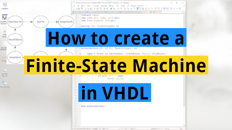
How to create a finite-state machine in VHDL
A finite-state machine (FSM) is a mechanism whose output is dependent not only on the current state of the input, but also on past input and output values. Whenever you need to create some sort of time-dependent algorithm in VHDL, or if you are faced with the problem of implementing a computer program in an…
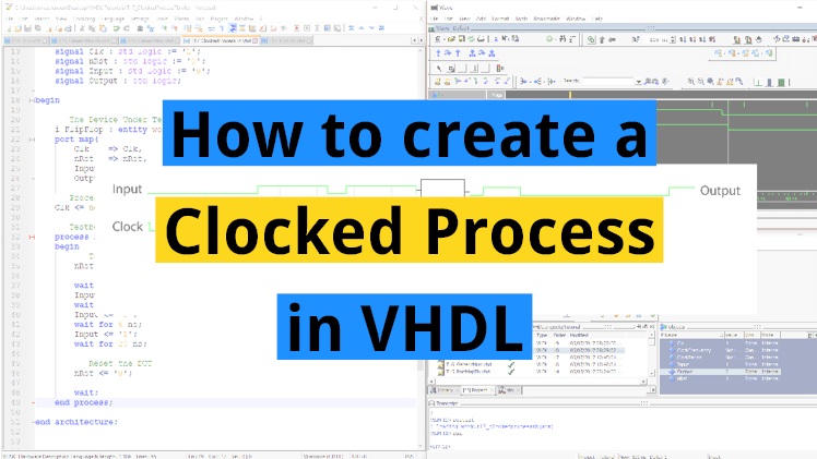
How to create a clocked process in VHDL
The vast majority of VHDL designs uses clocked logic, also known as synchronous logic or sequential logic. A clocked process is triggered only by a master clock signal, not when any of the other input signals change. The basic building block of clocked logic is a component called the flip-flop. There are different variants of…
Though those two codes are logically equivalent, the right one infers a transparent latch, it shouldn’t be used for synthesis.
I don’t think it does, but I’m not 100% sure what the synthesis tools do all the time.
This will infer a latch:
process(InSig) is
begin
    if InSig = '0' then
        OutSig <= '1';
    end if;
end process;
This shouldn’t create any latches:
process(InSig) is
begin
    OutSig <= '0';
    if InSig = '0' then
        OutSig <= '1';
    end if;
end process;
A link to the question:
https://vhdlwhiz.com/wp-content/uploads/2017/09/quiz_part-2-q6.png
Hi sir, You designed this course very well and advanced. I am happy to recommend this course to my friends.
I’m glad you enjoyed it! And thanks for taking the time to leave a nice comment.