UVVM results in faster and better FPGA verification
How UVVM lets FPGA designers control multiple interfaces simultaneously in VHDL testbenches, reducing verification time and catching more bugs.

How UVVM lets FPGA designers control multiple interfaces simultaneously in VHDL testbenches, reducing verification time and catching more bugs.
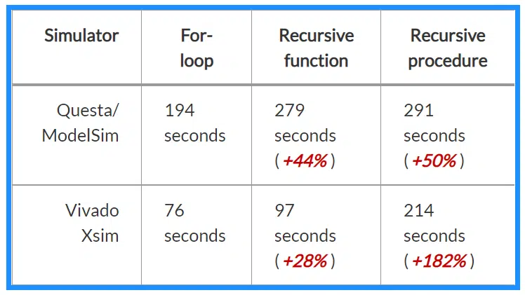
There are controversies in the VHDL community about how you can and shouldn’t use subprograms. Some say you should avoid using functions or procedures in synthesizable (RTL) code. While there are debatable subjective reasons to restrict the use of subprograms, many of these beliefs stem from myths or misconceptions. Therefore, I’m writing this article to…
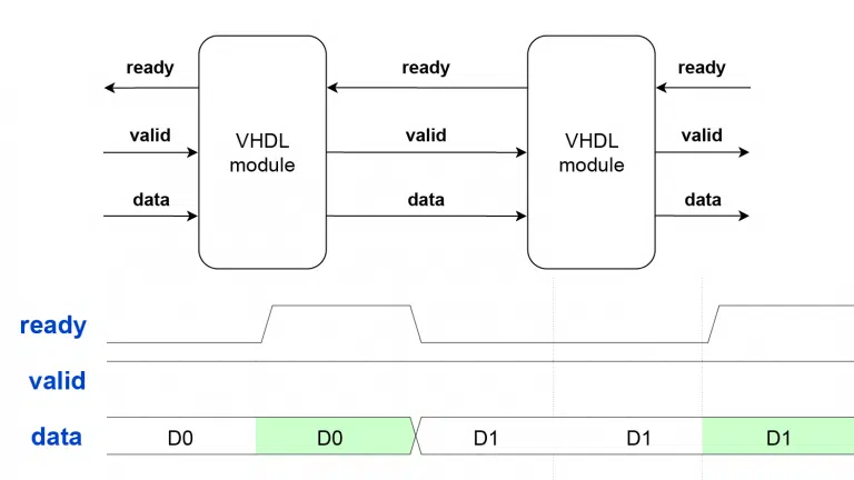
The ready/valid hardware data transfer protocol is simple and ingenious, providing flow control with only two control signals. The rules are straightforward: data transfer only happens when both ready and valid are ‘1’ during the same clock cycle.
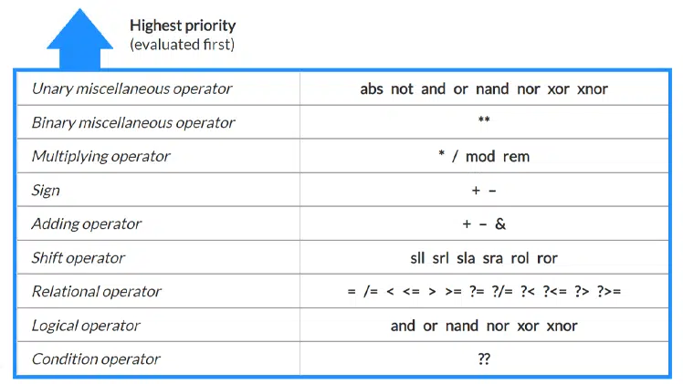
VHDL groups operators into classes with different precedence levels. Operators are evaluated according to their classes, starting with the highest level. Operators of the same class don’t have any predefined priority. Instead, they are evaluated left to right in the order they appear in the code.
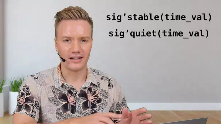
The ‘stable and ‘quiet attributes are predefined in the VHDL standard and work on signal objects. We can use these special features in simulation to check that a signal’s value remains untouched for a given period.
Many people struggle to understand the ModelSim/QuestaSim VHDL simulator’s workflow. I think that’s unnecessary because the basic workflow isn’t hard to learn. I regard the graphical user interface (GUI) as a front-end for the commands listed in this article. For example, when you click the Compile button in the ModelSim GUI, it runs the vcom…
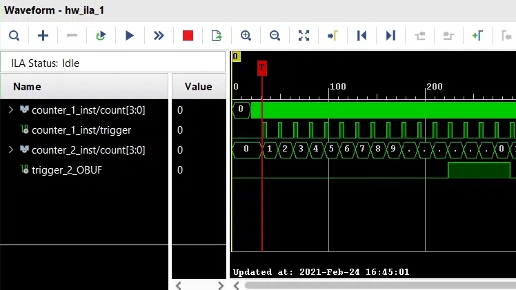
This tutorial covers using the Integrated Logic Analyzer (ILA) and Virtual Input/Output (VIO) cores to debug and monitor your VHDL design in the Xilinx Vivado IDE. In many cases, designers are in need to perform on-chip verification. That is, gaining access to an internal signal’s behavior in their FPGA design for verification purposes. One option…

A latch is a logic element that can sample and hold a binary value, much like a flip-flop (register). But unlike a flip-flop, which is edge-triggered, the latch is level-triggered.
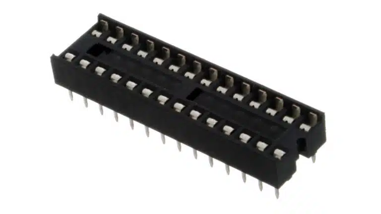
There are two ways to instantiate a module in VHDL: component instantiation and entity instantiation. Some people refer to the latter as direct instantiation. Entity instantiation didn’t exist in the first revisions VHDL, but it has been available since VHDL’93. This is the method that I recommend unless you have specific reasons to use component…
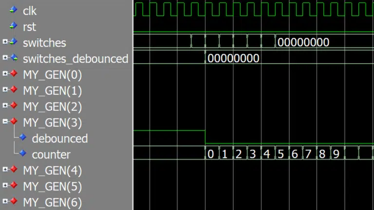
The generate statement in VHDL can automatically duplicate a block of code to closures with identical signals, processes, and instances. It’s a for loop for the architecture region that can create chained processes or module instances.
End of content
End of content